

Electrical heater, heating heat exchanger and vehicle air conditioner
An electric heater and heat technology, applied in air heaters, heat exchanger shells, fluid heaters, etc., can solve problems such as complex heater structures
- Summary
- Abstract
- Description
- Claims
- Application Information
AI Technical Summary
Problems solved by technology
Method used
Image

Examples
no. 1 example
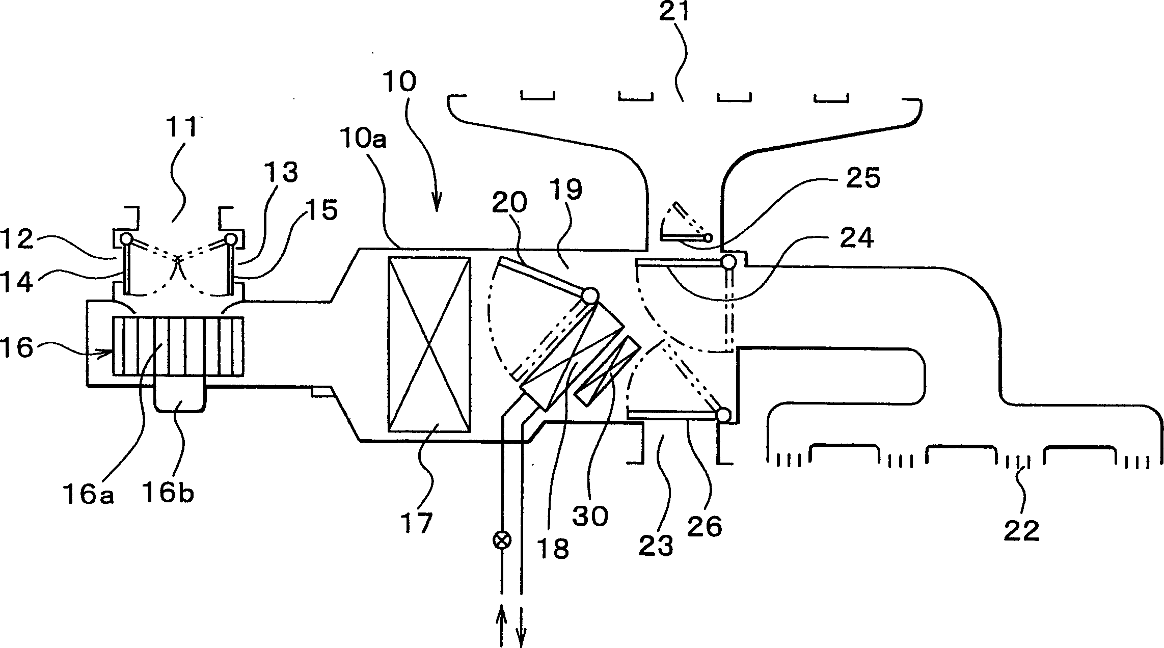
[0030] The following will refer to the attached figure 1 and 2 A first embodiment of the present invention will be described. First, an air conditioner for a vehicle using the electric heater of the first embodiment will be described. figure 1 A schematic structure of an interior air conditioning unit portion 10 of an air conditioner for a vehicle is shown. The interior air-conditioning unit section 10 is generally installed inside an unshown vehicle instrument panel (instrument panel), which is located at the front of the passenger compartment of the vehicle. Outer air inlets 11, inner air inlets 12, 13 and inner and outer air switch doors 14, 15 for opening and closing these inlets 11, 12, 13 are located in the air flow of the inner air conditioning unit portion 10. the most upstream part.
[0031] The outside air (i.e., the air outside the passenger compartment of the vehicle) or the inside air (i.e., the air inside the passenger compartment of the vehicle) entering fro...
no. 2 example
[0051] The following will refer to image 3 A second embodiment of the present invention will be described.
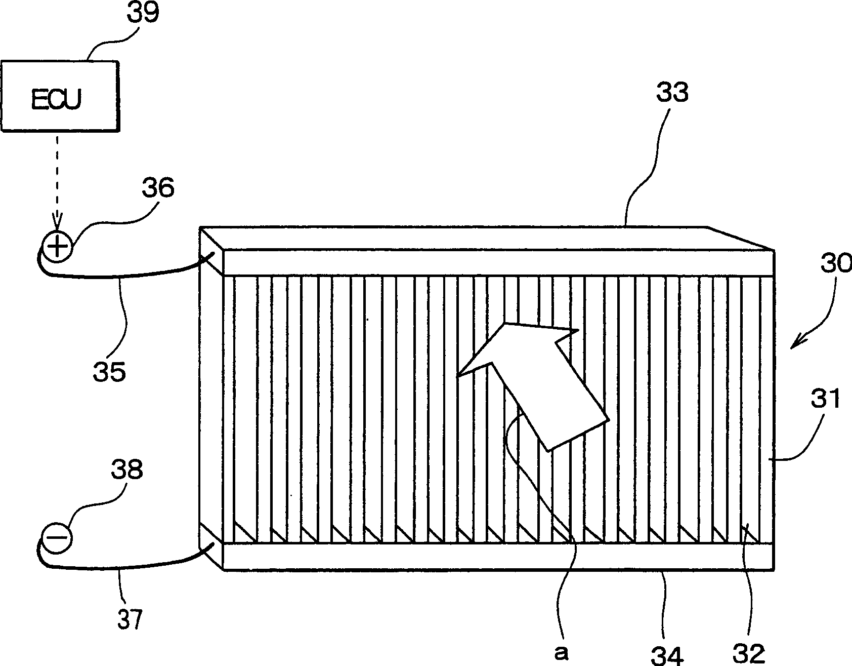
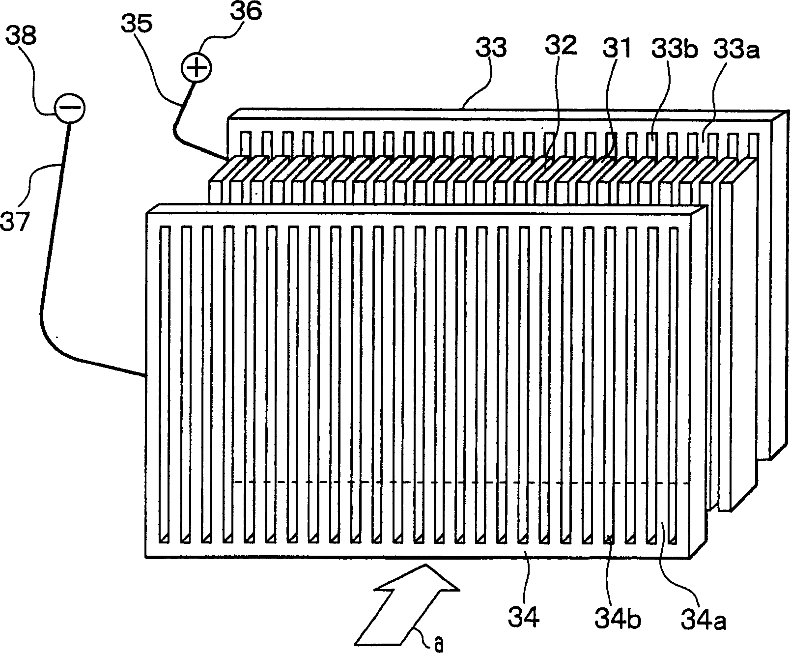
[0052] In the first embodiment described above, the electrode members 33, 34 are located in the longitudinal direction of each of the plurality of heating body plates 31 ( figure 1 The two ends on the vertical direction). That is, the electrode members 33 and 34 extend in a direction parallel to the airflow direction "a" at both ends of each heating body plate 31 . But in the second embodiment, as in image 3 As shown, the electrode members 33 and 34 are located at both end portions of each heating body plate 31 in the short side direction (horizontal direction). That is, the electrode parts 33 , 34 are located at the upstream and downstream end portions of the heating body plate 31 in the airflow direction “a”.
[0053] Therefore, in the second embodiment, the segment-shaped joint portions 33a, 34a and the slit-shaped air gap portions 33b, 34b are formed in the el...
no. 3 example
[0056] The following will refer to Figure 4A and 4B A third embodiment of the present invention will be described.
[0057] In the above-mentioned first and second embodiments, the heating body plate 31 and the electrode parts 33, 34 are pre-molded independent bodies respectively, and the ends of a plurality of heating body plates 31 arranged parallel to each other are connected to the electrode parts 33 in a flat plate shape. , 34 joined into a whole. But in the third embodiment, if Figure 4A and 4B As shown, auxiliary electrode parts 330 and 340 made of electrical conductors such as copper are integrally molded at the end of each heating body plate 31 .
[0058] In particular, in Figure 4A Among them, the auxiliary electrode members 330, 340 made of conductors such as copper and the longitudinal direction of each heating body plate 31 ( figure 1 The two ends in the vertical direction) are molded into one piece. In addition, in Figure 4B Among them, the auxiliary ...
PUM
 Abstract
Description
Claims
Application Information