Capacitive sensor

A capacitive sensor, sensor technology, applied in the direction of sensor, capacitance measurement, using electric/magnetic device to transfer sensing components, etc.

Inactive Publication Date: 2005-02-09
ALPS ALPINE CO LTD
View PDF2 Cites 17 Cited by
  • Summary
  • Abstract
  • Description
  • Claims
  • Application Information

AI Technical Summary

Problems solved by technology

[0007] The present invention is proposed in response to the above problems, and its purpose is to provide a capacitive sensor that is not easily affected by noise, and does not have the problem of leakage current or feedthrough of switching transistors, and can reliably capture tiny capacitance sensors.

Method used


Image

  • Capacitive sensor
  • Capacitive sensor
  • Capacitive sensor

Examples


Embodiment Construction

[0034] Hereinafter, a first embodiment of the present invention will be described with reference to the drawings.

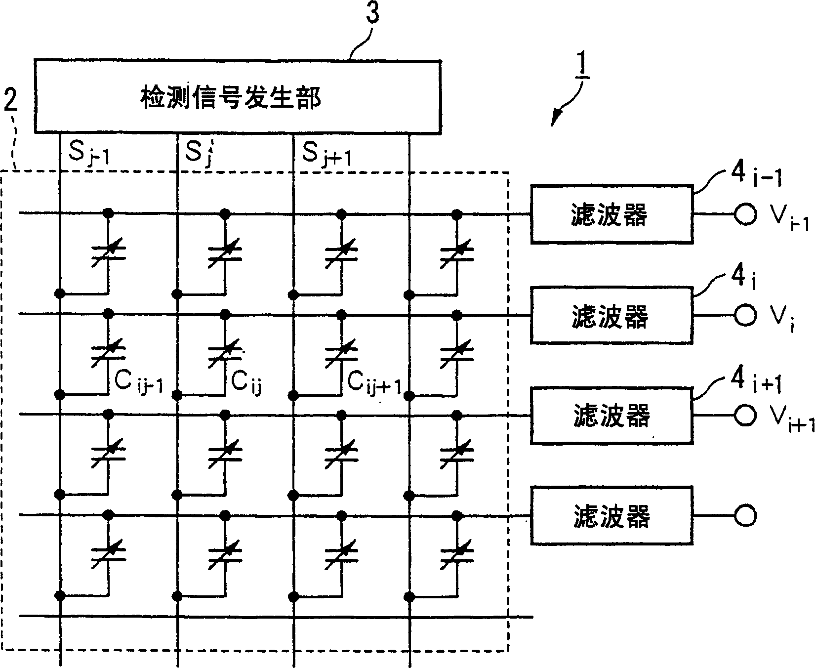
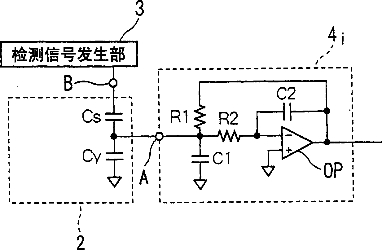
[0035] figure 1It is a block diagram showing the structure of the capacitance sensor 1 of this embodiment. The capacitive sensor 1 shown in this figure is composed of a sensor unit 2 that touches an object to be detected (for example, a finger), a detection signal generation unit 3 that outputs a detection signal to the sensor unit 2, and a filter 4i that receives an output signal from the sensor unit 2. -1, 4i, 4i+1, ... and processing circuits (not shown) for processing the outputs of 4i-1, 4i, 4i+1, ....

[0036] Regarding the sensor part 2, first and second flexible thin plate bodies are arranged at a slight interval, and a plurality of column wirings are formed at equal intervals on the first thin plate body, and a plurality of column wirings are formed on the second thin plate body at equal intervals along the A plurality of row wirings are formed in a d...


PUM


Abstract

A pressure-sensitive capacitive sensor includes a sensing unit in which a plurality of column wires and a plurality of row wires are formed in a matrix, a detecting signal generator, and filters. Capacitances at intersections between the column wires and the row wires change in accordance with externally applied pressure. The detecting signal generator sequentially outputs pulse signals of a predetermined frequency to the column wires of the sensing unit. The filters are connected to the respective row wires of the sensing unit and extract amplitudes of signals of the predetermined frequency. The amplitude is proportional to the capacitance at the intersection.

Description

technical field [0001] The present invention relates to a capacitive sensor primarily used as a fingerprint sensor. Background technique [0002] In the past, as the most promising fingerprint sensor in the biometric authentication technology, column wiring and row wiring were formed on the surface of two thin films at a predetermined interval, and the array wiring was arranged opposite to each other at a predetermined interval through an insulating film or the like. Thin film pressure sensitive capacitive sensor. When putting a finger on this pressure-sensitive capacitive sensor, the shape of the film is deformed corresponding to the shape of the fingerprint, and the interval between the column wiring and the row wiring varies by area. The capacitance of the intersection point is used to detect the shape of the fingerprint. In this piezo-sensitive capacitive sensor, as can be applied to detect less than several hundred fF (femto farad, 10 -15 Farad) capacitance of the co...

Claims


Application Information

Patent Timeline
Patent Type & Authority Applications(China)
IPC IPC(8): G01L5/00A61B5/117G01B7/28G01D5/24G01L9/12G01R27/26G06F3/041G06F3/044G06K9/00G06T1/00
CPCA61B5/1172G06F3/0414G01L9/12G06K9/0002G01R27/2605G06F3/044G06F3/0446G06V40/1306G01R23/165
Inventor 斋藤润一梅田裕一
Owner ALPS ALPINE CO LTD
Why Eureka
Try Eureka