
Client network interface method using ethernet line as IP control channel

A technology of control channel and network interface, applied in the field of physical realization of client network to interface in automatic switching optical transport network, can solve problems such as lack of clear explanation, and achieve the effect of timely processing, high reliability and rapid response

Inactive Publication Date: 2005-02-16
FENGHUO COMM SCI & TECH CO LTD
View PDF1 Cites 4 Cited by
  • Summary
  • Abstract
  • Description
  • Claims
  • Application Information

AI Technical Summary

Problems solved by technology

However, this patent does not clearly explain the specific implementation of the UNI channel, the corresponding encapsulation protocol of the UNI signaling, the transmission process of the UNI signaling, and the specific connection mode inside the ASON node.

Method used

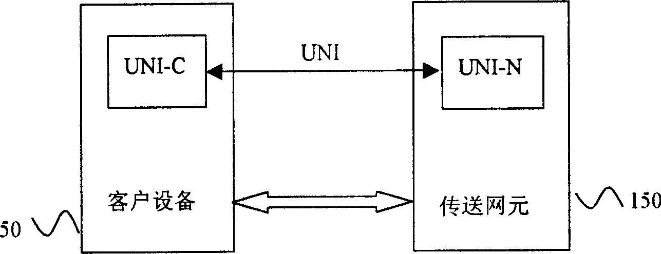
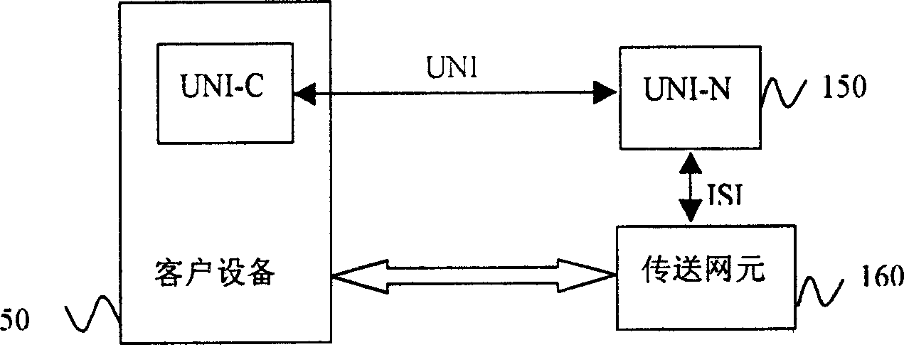
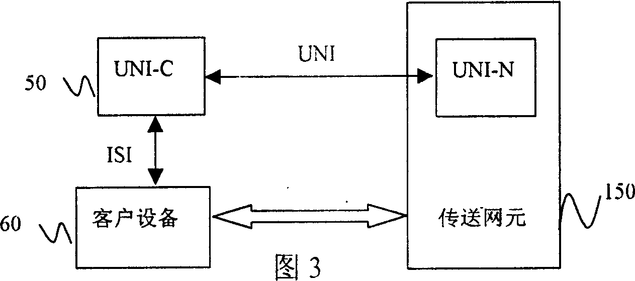

Image

  • Client network interface method using ethernet line as IP control channel
  • Client network interface method using ethernet line as IP control channel
  • Client network interface method using ethernet line as IP control channel

Examples


Embodiment Construction

[0027] Figure 5 The hardware design scheme of the UNI interface using the Ethernet cable as the IP control channel is given: the Ethernet cable 200 is used to connect the RJ-45 Ethernet port (10M / 100M) on the customer's UNI agent 50 and the RJ-45 port of the ASON control unit on the SDH network node. 45 Ethernet ports (10M / 100M), used to provide dedicated IP control channel. The ASON control unit 151 communicates with the controlled single disk through a layer 2 Ethernet switch or switching HUB 152 and a backplane communication bus 300 . The data channel is realized by connecting the optical or Ethernet interface 61 of the client device 60 to the optical or Ethernet interface 160 on the interface board 159 of the network node 150 .

[0028] Figure 6 Describes the UNI interface hardware design scheme in which the customer equipment and the transmission network element are in the same equipment: use Ethernet cable 200 to connect the RJ-45 Ethernet port (10M / 100M) on the cust...


PUM


Abstract

Data link and IP control channel are transferred separately. Client proxy at client end UNI-C and network node end is connected through Ethernet channel to provide dedicated IP control channel. Network node is automatic switch optical network (ASON) node. Two layer Ethernet exchanger or exchange type HUB inside network node communicates to ASON control unit through communication bus at back plate. Information of UNI-C control signaling through Ethernet wire is transferred to ASON control unit. Based on signaling requirement, ASON control unit through two layer Ethernet exchanger or exchange type HUB and single disk communication bus inside node controls each single disk inside node to carry out relevant operation.

Description

technical field [0001] The invention relates to a client network interface method using an Ethernet line as an IP control channel, which belongs to the physical realization method of a client network-to-interface (UNI) on an automatic switching optical transmission network, and can be applied to various types of clients accessing an automatic switching optical network application occasions. Background technique [0002] Automatically Switched Optical Network (ASON) introduces the control plane in the traditional SDH (Synchronous Digital Hierarchy) and OTN (Optical Transport Network), thus bringing a revolutionary change to the Optical Transport Network. The ASON network supports three connection modes: switched connection, soft-permanent connection and provisioned permanent connection. Among them, the switched connection can make the user automatically request the optical channel connection, so as to provide customers with faster channel establishment, more flexible network...

Claims


Application Information

Patent Timeline
IPC IPC(8): H04L12/24H04L29/02H04Q3/00
Inventor 魏学勤王志峰雷荣华刘翔宇吴兵波谢秋红
Owner FENGHUO COMM SCI & TECH CO LTD
Learn More