Gear and rack type cooker hood

A technology of rack and pinion and pumping unit, which is applied in the direction of liquid variable displacement machinery, mechanical equipment, machine/engine, etc., which can solve the problems of low mechanical efficiency, high manufacturing cost, and difficulty in adjusting the number of strokes, and achieve the mechanical transmission route Short, easy to manufacture and install, convenient and quick to adjust parameters

Inactive Publication Date: 2005-02-23
王胜青
View PDF0 Cites 14 Cited by
  • Summary
  • Abstract
  • Description
  • Claims
  • Application Information

AI Technical Summary

Problems solved by technology

[0002] In the petroleum industry, the pumping units in the prior art all have relatively serious defects that are difficult to overcome by themselves.
The beam pumping unit has short stroke, poor balance effect, low system efficiency, and it is difficult to adjust the stroke and stroke times; the mechanically reversing non-beam pumping unit (such as chain type, belt type) has large reversing impact, and the mechanism Poor stress condition, low mechanical efficiency, many wearing parts, high manufacturing cost, short life, unable to adjust stroke, and difficult to adjust stroke times; non-mechanical reversing beamless pumping unit (such as friction reversing type) Then, due to the relative sliding and friction between the driving wheel (or drum) and the wire rope (or belt), the wear of the machine parts will increase, the mechanical efficiency will be reduced, and the movement accuracy of the mechanism will be poor, which will easily cause the upper and lower dead centers of the stroke to change, or even lead to downhole accidents
Moreover, it is difficult to install and disassemble the counterweight box, and it is inconvenient to install, use and maintain

Method used


Image

  • Gear and rack type cooker hood

Examples


Embodiment approach

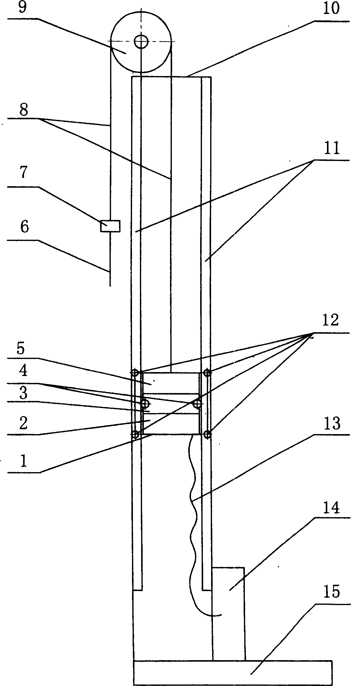
[0014] It can be seen from the figure that a motor 5, a reducer 3, a brake 2 and a guide wheel 12 are installed at the counterweight reciprocating frame 1. The rope hanger 7 is connected with the polished rod 6, the output gear 4 of the reducer 3 is engaged with the rack guide rail 11 installed at the frame 10; the motor 5 is connected with the controller 14 through the accompanying cable 13, and the pulley 9 is installed at the frame 10 . Each part of the counterweight reciprocating frame 1 can be installed separately or partly integrated and integrally installed as a whole reciprocating frame part. The output gear 4 of the reducer 3 meshes with the rack guide rail 11 installed on the frame 10. There are 1 to 2 or more gears. It is 1 to 2 or more, and the tooth shape of the gear and rack is straight, helical or herringbone-shaped switched reluctance motor or DC motor for speed regulation; reducer 3 can use worm gear reducer, gear reducer or planetary cycloid reducer; the br...


PUM


Abstract

A gear-rack type oil sucker consists of a frame, a gear and a rack, pulleys, a reciprocal frame for weight, and a controller. The reciprocal frame for weight consisting of a motor, a speed reducer, a brake and guide pulleys, is installed on the rack railing. A steel rope is connected with polish rod via the pulleys and rope-suspending device. The speed reducer has an output gear installed on the said frame to engage with the rack railing. The motor is connected with controller via its electric cables. The pulleys are arranged on the frame top. The oil sucker has simple and compact structure, strong bearing capacity, efficient transmission, long service life, and is reliable and easy in use, installation and maintenance, substitute as upgraded products.

Description

1. Technical field: [0001] The invention belongs to oil production equipment in the field of petroleum industry, and relates to an oil pumping unit for mechanical oil production in an oil field, in particular to a beamless pumping unit. 2. Background technology: [0002] In the petroleum industry, the pumping units in the prior art all have their own relatively serious defects that are difficult to overcome. The beam pumping unit has short stroke, poor balance effect, low system efficiency, and it is difficult to adjust the stroke and stroke times; the mechanically reversing non-beam pumping unit (such as chain type, belt type) has large reversing impact, and the mechanism Poor stress condition, low mechanical efficiency, many wearing parts, high manufacturing cost, short life, unable to adjust stroke, and difficult to adjust stroke times; non-mechanical reversing beamless pumping unit (such as friction reversing type) Then, due to the relative sliding and friction between ...

Claims


Application Information

Patent Timeline
Patent Type & Authority Applications(China)
IPC IPC(8): E21B43/00F04B47/02
Inventor 王胜青王维星刘明华
Owner 王胜青
Why Eureka
Try Eureka