Supercharge Your Innovation With Domain-Expert AI Agents!

Method for driving LED by current mirror

A technology of light-emitting diodes and current mirrors, applied in the field of current mirror-driven light-emitting diodes, can solve problems such as high power loss

Inactive Publication Date: 2005-02-23
ANALOG INTEGRATIONS CORP
View PDF0 Cites 4 Cited by
  • Summary
  • Abstract
  • Description
  • Claims
  • Application Information

AI Technical Summary

Problems solved by technology

Since the control method of the charge pump circuit for the current mirror is to V OUT fixed at 5V, while the input voltage of the white LED D35 is V F It is between 3.1~3.8V, so there will be too much power loss on the current mirror, that is

Method used


Image

  • Method for driving LED by current mirror
  • Method for driving LED by current mirror
  • Method for driving LED by current mirror

Examples


Embodiment Construction

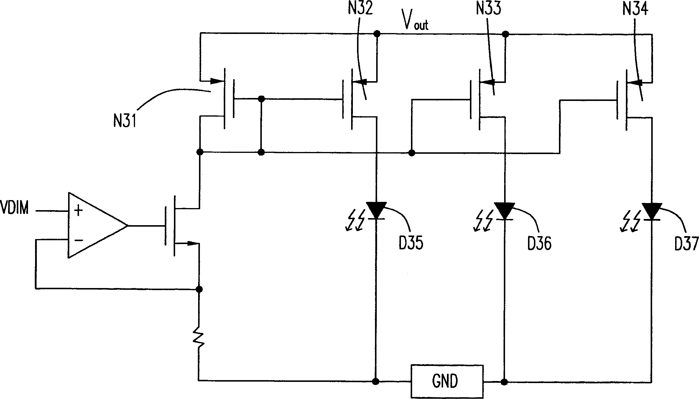
[0034] see Figure 4 , which is a circuit diagram of a preferred implementation of the method for driving a light-emitting diode with a current mirror in the present invention. It uses an inductive boost circuit 40 to boost the voltage at the input terminal of the current mirror 41 to drive the LED coupled to the current mirror 41. A plurality of light-emitting diodes (LEDs) at the output end, as for the color of the light source of the light-emitting diodes, it is not limited to white light, blue light or even light-emitting diodes of other colors can be applied to the method described in the present invention; and for the convenience of explanation and drawing, this The embodiment is only described by using four identical metal-oxide-semiconductor transistors (MOS) current mirrors 41 and three parallel-connected white light emitting diodes. Circuit configuration method of light emitting diode.

[0035] exist Figure 4 Among them, the inductive boost circuit 40 is composed ...


PUM


Abstract

The invention relates to a method for driving LED by current mirror by using high-efficiency boost circuit, and the method is used for driving plural LEDs parallel connected to output terminals of a current mirror. To obtain most efficient output, operation manner includes following steps: using voltage of control terminal of the current mirror as reference voltage; boosting input terminal voltage of the current mirror, and using the input terminals of the plural LEDs as voltage feedback point to fix voltage difference between the input terminal and the output terminal of the current mirror; using the output terminal voltage of the current mirror to drive the plural LEDs.

Description

(1) Technical field [0001] The invention refers to a method for driving a light-emitting diode (LED) with a current mirror, especially a method for driving a white light-emitting diode with a current mirror. (2) Background technology [0002] The current boost method used in the market to drive white light-emitting diodes (LEDs) with a current mirror is a common charge pump circuit (Charge Pump Circuit), such as figure 1 As shown, it uses the unidirectional transmission characteristics of diode-connected MOS and capacitance to transmit and store charge to generate high voltage output; the traditional charge pump circuit is composed of several basic pump circuits 11 connected in series , and each basic pump circuit is formed by coupling the first capacitor C22, the first transistor N23, the second capacitor C25 and the second transistor N26. Wherein, the first transistor N23 and the second transistor N26 are firstly connected to form a common drain, and then respectively con...

Claims


Application Information

Patent Timeline
Patent Type & Authority Applications(China)
IPC IPC(8): H05B37/00H05B44/00
Inventor 李明儒冯蔚文
Owner ANALOG INTEGRATIONS CORP
Features
  • R&D
  • Intellectual Property
  • Life Sciences
  • Materials
  • Tech Scout
  • Unparalleled Data Quality
  • Higher Quality Content
  • 60% Fewer Hallucinations
Learn More