Eureka AIR delivers breakthrough ideas for toughest innovation challenges, trusted by R&D personnel around the world.

Monitoring method and device for laser phase Doppler powder dust particle

A Doppler dust and particle monitoring technology, which is applied in measuring devices, color/spectral characteristic measurement, particle size analysis, etc., can solve problems such as small measurement range, low instrument sensitivity, beam spot expansion measurement error, etc., and achieve measurement accuracy and The effect of high spatial resolution, high measurement accuracy and wide measurement range

Inactive Publication Date: 2005-03-02
TIANJIN UNIV
View PDF0 Cites 10 Cited by
  • Summary
  • Abstract
  • Description
  • Claims
  • Application Information

AI Technical Summary

Problems solved by technology

However, due to the complexity of the light scattering phenomenon, the scattering attenuation caused by particles is only a qualitative value about the particle concentration, and often has a multi-valued relationship due to the difference in size distribution.
Second, this test method does not allow the measurement of particle velocity, which is a key parameter for measuring emissions
At the same time, the light scattering intensity is easily disturbed, and the possible beam expansion and drift caused by the particle flow will bring errors to the measurement.
Since it is impossible to know the information about the composition of dust emissions such as dust particle size, size distribution, and particle flight speed, the dust emission data obtained by existing instruments are only dust emission parameters (such as TSP, PM, etc.) obtained through calibration. 10 , PM 2.5 , PM 1 etc.), the sensitivity of the instrument is low, and the measurement range is small, so it must be calibrated and adjusted frequently to ensure the reliability of the test data

Method used


Image

  • Monitoring method and device for laser phase Doppler powder dust particle
  • Monitoring method and device for laser phase Doppler powder dust particle
  • Monitoring method and device for laser phase Doppler powder dust particle

Examples


Embodiment Construction

[0016] Below in conjunction with the discharge dust monitoring to certain coal-fired boiler, the implementation process of the present invention is described in detail:

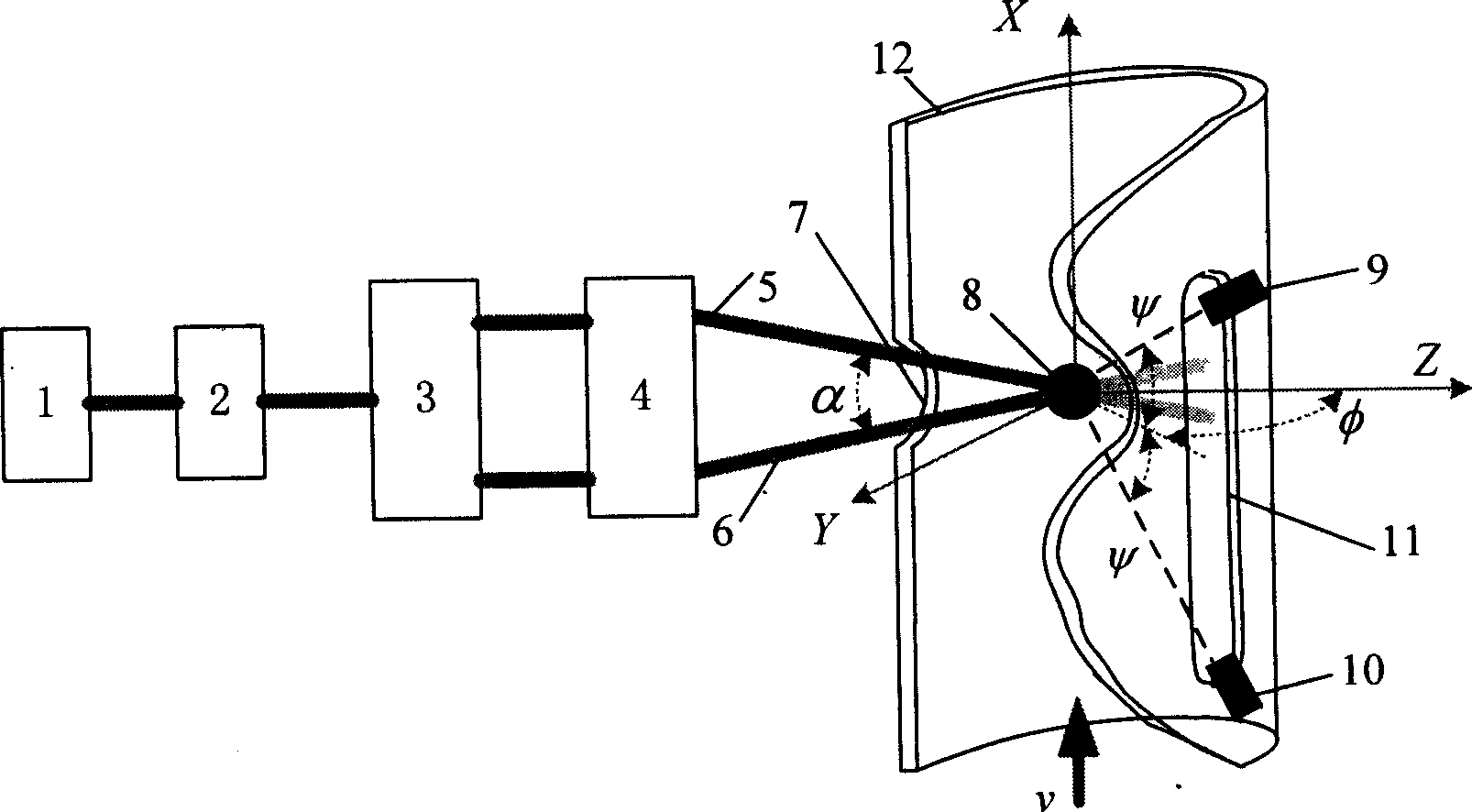
[0017] During the monitoring process of the dust discharge of a coal-fired boiler, the optical detection system of the device of the present invention is installed on the boiler dust discharge channel 12 (as attached figure 2 As shown), the diameter of the channel is 800mm, a round hole 7 is opened on the incident light side, and a long hole 11 is opened on the side receiving the scattered light. Both holes are inlaid with transparent materials. The single-frequency laser output by the laser 1 is converted into two coherent beams with equal intensity by the polarizer 2 and the beam splitter 3. After being focused by the objective lens 4, the two coherent incident beams 5 and 6 are converged at the discharge dust particle flow 8 at an angle α .

[0018] The two APD detectors 9 and 10 receive scattered light ...


PUM


Abstract

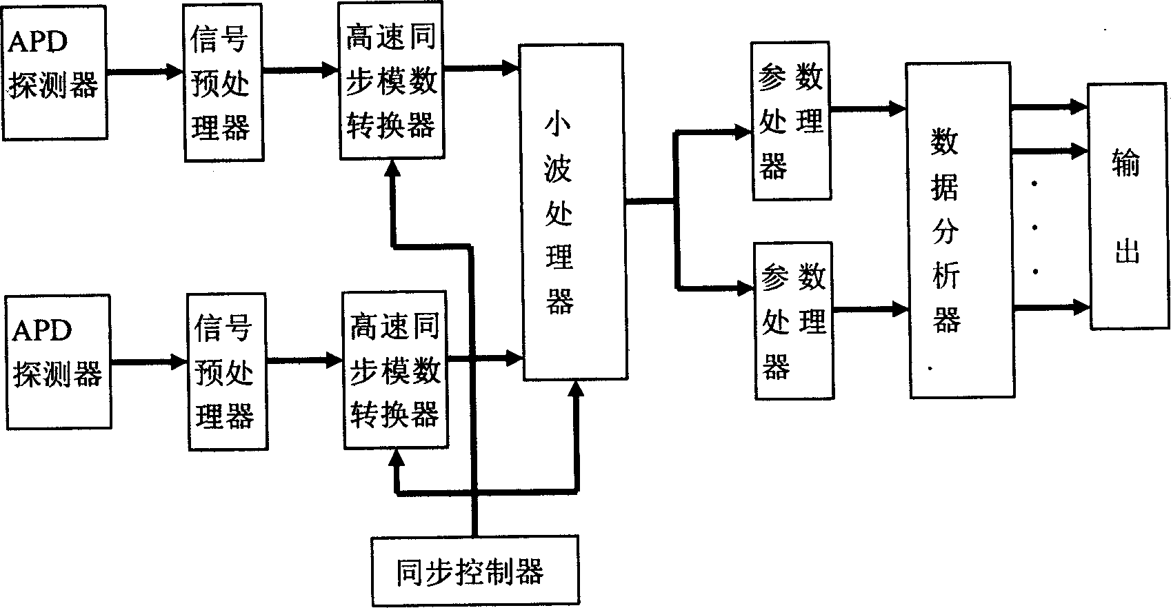
A laser phase Doppler dust particle monitoring method and apparatus belongs to particle measuring technique. It includes the steps that two beams of coherent incident light has concourse and irradiate normally to flowing direction of dust particle current; two sensors are installed with symmetry, optical signal of particle scattering received by which has the same frequency but different phase, its frequency is proportional to flight velocity of particle and phase difference is proportional to with diameter of particle, by using processor to extract frequency and phase difference of signal, the diameter, velocity and other information of particle are obtained. The apparatus consists of detecting system containing laser source, polarizer, beam splitter, objective lens and APD sensor and processing system containing signal preprocessor, high speed synchronous A / D converter, wavelet processor, parameter processor and data fractional, synchronous controller. The invention has the advantages including high accuracy and reliability of parameter measurement like velocity and diameter of dust particle, wide measuring range and excellent applicability.

Description

technical field [0001] The invention relates to a laser phase Doppler dust particle monitoring method and device, belonging to the particle measurement technology. Background technique [0002] my country's air pollution is mainly sulfur dioxide and solid particles produced by coal burning. Air quality is related to total suspended particles (TSP) and floating dust, which measure the concentration of solid particles. Therefore, dynamic monitoring of the emission rate of dust in the atmosphere and the composition of dust particles is of great significance. In the process of environmental monitoring, people not only care about the physical size and distribution of dust particles, but also care about the speed of movement of dust particles. [0003] At present, the principle of optical scattering detection is mainly used for dynamic monitoring and measurement of dust emissions, and the detector is used to detect the degree of absorption of emitted light ...

Claims


Application Information

Patent Timeline
Patent Type & Authority Applications(China)
IPC IPC(8): G01N15/00G01N15/02G01N15/06G01N21/31G01N21/49
Inventor 曾周末李健张慧靳世久
Owner TIANJIN UNIV
Why Eureka
Eureka Blog
Learn More