Radio frequency band low temperature low noise amplifier

A low-noise amplifier and amplifier technology, applied to high-frequency amplifiers, improved amplifiers to reduce noise effects, etc., can solve the problems of amplifiers deviating from the operating point and not working normally, achieve small standing wave ratio, high sensitivity, and reduce overall noise Effect

Inactive Publication Date: 2005-03-02
TSINGHUA UNIV
View PDF0 Cites 12 Cited by
  • Summary
  • Abstract
  • Description
  • Claims
  • Application Information

AI Technical Summary

Problems solved by technology

At present, the existing amplifier circuit is designed for the normal temperature environment. Since the S parameter of the amplifier tube will change with the temperature, the amplifier deviates from the operating point at low temperature and cannot work normally.

Method used


Image

  • Radio frequency band low temperature low noise amplifier
  • Radio frequency band low temperature low noise amplifier
  • Radio frequency band low temperature low noise amplifier

Examples


Embodiment Construction

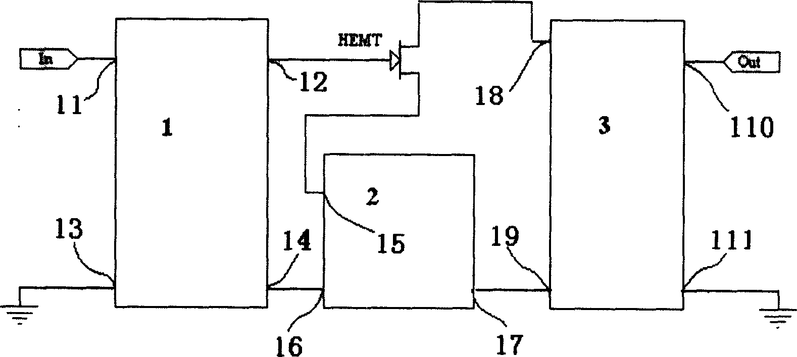
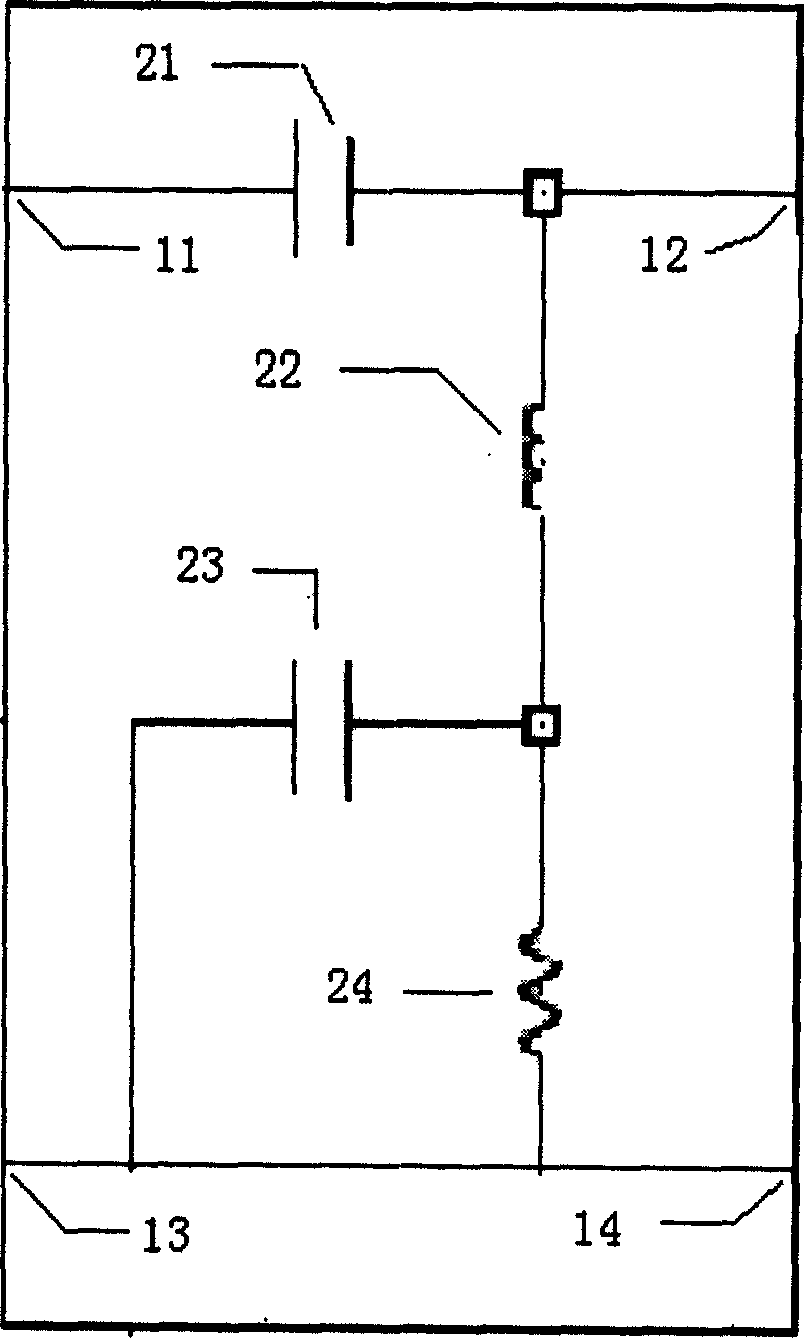
[0009] The invention is a radio frequency low-temperature low-noise amplifier for realizing ultra-high sensitivity of the front-end system of a high-temperature superconducting receiver, and achieving extremely low noise coefficient and low input voltage standing wave ratio in a superconducting environment. figure 1 The schematic diagram of the RF low-temperature low-noise amplifier is shown, and its amplifying circuit is divided into input matching network 1, output matching network 3, and negative feedback network 2 according to the different pins connected to the transistor. Among them, points 13, 14, 16, 17, 19, and 111 represent the grounding points of the circuit; points 11, 12, 15, 18, and 110 represent the signal points connected to each network.

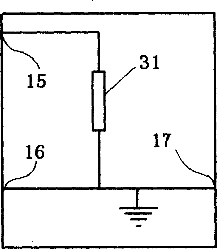
[0010] This amplifier uses a microstrip line grounded at one end as the source negative feedback circuit 2 (such as image 3 Shown), improve the stability of the amplifier, while enabling the circuit to have low noise and in...


PUM


Abstract

This invention relates to RF range low-temp.l low-noise amplifier. According the connections of the feet of transistors, the types of the amplifier circuits are: input matching network, output matching network and negative feed-back network. This ivnented product can reduce noise of front part of the super-conduction receiver and to realize high sensitivity of the front part of the super-conduction receiver. It has advantages of small standing-wave retio (SWR), small size, long term stable working, e.g. when used ni CDMA, the SWR of input voltage <1.3, the output SWR<2.5, noise coefficient <0.3 dB, and long period working under 72K.

Description

technical field [0001] The invention belongs to the field of amplifiers in radio frequency technology, in particular to a radio frequency low-temperature low-noise amplifier. Background technique [0002] Amplifying circuit is a main microwave circuit, which amplifies the required microwave signal from noise and interference and sends it to the subsequent circuit for processing. Processing gain is an important indicator of the amplifying circuit, and at the same time, it is necessary to minimize the useless components mixed in the signal. Noise is a time-domain statistical indicator. The noise figure is an indicator used to measure the proportion of circuit additive noise in the overall noise. It is defined as the ratio of the input signal-to-noise ratio to the output signal-to-noise ratio. Noise figure is generally a relative value scaled in dB. A good amplifier circuit requires an extremely low noise figure to achieve noiseless amplification. The existing amplifier circ...

Claims


Application Information

Patent Timeline
Patent Type & Authority Applications(China)
IPC IPC(8): H03F1/26H03F3/189
Inventor 曹必松张晓平王凡郜龙马高葆新
Owner TSINGHUA UNIV
Why Eureka
Try Eureka