Well drilling pump piston

A technology for drilling pumps and pistons, which is applied in the field of pistons used in single-acting mud pumps. It can solve the problems that air cannot be completely prevented from entering the cylinder liner, water hammer cannot be effectively solved, and water hammer cannot be completely eliminated. Shock phenomenon, reduce maintenance time, facilitate the effect of industrial production

Inactive Publication Date: 2005-03-09
陈勇
View PDF0 Cites 5 Cited by
  • Summary
  • Abstract
  • Description
  • Claims
  • Application Information

AI Technical Summary

Problems solved by technology

Since the seal between the piston and the cylinder liner is only realized by the rubber seal ring installed on the front part of the piston body, when the seal ring is deformed and a gap is formed between the cylinder liner, air will enter the cylinder liner, resulting in insufficient mud suction , resulting in water hammer
In order to prevent air from entering the cylinder liner, the measures taken in the prior art are to configure a spray pump to fill the gap between the rubber sealing ring and the cylinder liner with circulating water, but this measure cannot completely prevent air from entering the cylinder liner, so it cannot completely prevent air from entering the cylinder liner. To eliminate the occurrence of water hammer, in order to ensure the normal operation of the drilling mud pump, the measures taken in the prior art are to configure the mud injection pump
The rubber sealing ring installed on the front part of the piston body deforms more when the mud injection pump is not working properly, and the gap between it and the cylinder liner is also larger, resulting in more circulating water and the entrained sediment entering the cylinder. The sleeve not only produces water hammer, but also dilutes the mud, and the wear between the piston and the cylinder liner is accelerated, and the wear of the cylinder liner increases the gap between the piston and the cylinder liner, making the air, circulating water and sediment more Easy access to the cylinder liner, resulting in increasingly severe water hammer and wear of the cylinder liner, and may even cause a blowout
To sum up, the configuration of the spray pump and the mud injection pump cannot effectively solve the phenomenon of air entering the cylinder liner and the resulting water hammer. At the same time, it also accelerates the wear of the cylinder liner and increases the drilling cost

Method used


Image

  • Well drilling pump piston
  • Well drilling pump piston
  • Well drilling pump piston

Examples


Embodiment Construction

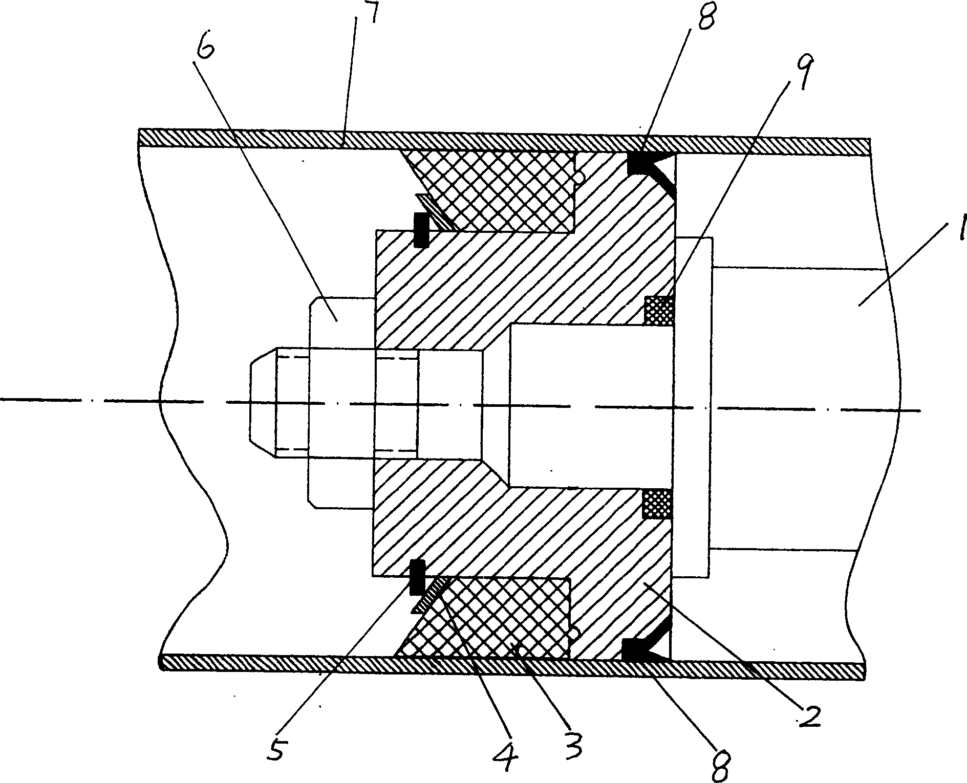
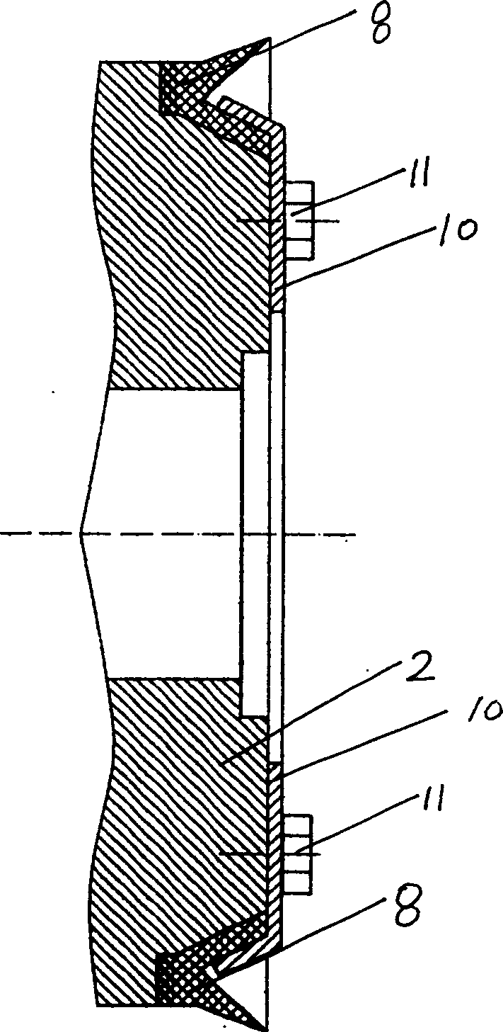
[0018] A specific structure of the novel drilling pump piston of the present invention is as follows: figure 1 As shown, it includes piston body 2, piston rod 1, rubber sealing ring 3, rubber sealing ring 9 and air sealing ring 8; the combined section of piston rod and piston body is processed with threads, and the piston body 2 and piston rod 1 pass through the nut 6 Realize threaded connection and combine into one; rubber sealing ring 3 is installed on the front section of the piston body, fixed with baffle plate 4 and circlip 5; rubber sealing ring 9 is installed on the contact surface between the piston body and the piston rod; air seal Ring 8 is a "V"-shaped rubber ring, which is fixedly connected to the rear end of the piston body with its opening facing away from the piston body. The fixed connection method is as follows: figure 2 As shown, the pressure plate 10 and the screw 11 are closely combined with the piston body.

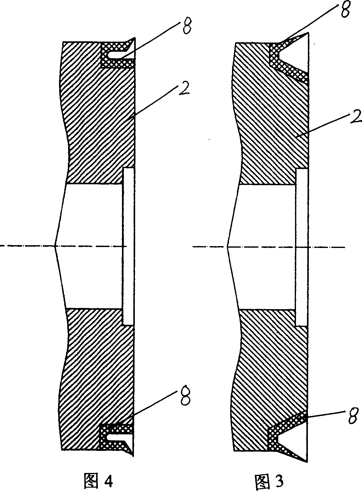
[0019] The air blocking ring 8 can also be a ...


PUM


Abstract

A piston for well-drilling pump is composed of main body, piston rod, sealing ring installed at front part of main body, the sealing ring positioned at the contact surface between main body and piston rod, and air blocking ring which is a V-shaped, trapezoidal or V-shaped rubber ring. Its advantages are no water hammer, and high sealing performance.

Description

technical field [0001] The invention belongs to a drilling pump piston used in oil exploration and drilling development, in particular to a single-acting mud pump piston. Background technique [0002] It is understood that the existing drilling pumps, such as the piston of the three-cylinder single-acting drilling mud pump, are mainly composed of a piston body, a piston rod, a rubber sealing ring and a rubber sealing ring. In the front section of the piston body, a rubber sealing ring is installed on the contact surface between the piston body and the piston rod. Since the seal between the piston and the cylinder liner is only realized by the rubber seal ring installed on the front part of the piston body, when the seal ring is deformed and a gap is formed between the cylinder liner, air will enter the cylinder liner, resulting in insufficient mud suction , resulting in water hammer. In order to prevent air from entering the cylinder liner, the ...

Claims


Application Information

Patent Timeline
Patent Type & Authority Applications(China)
IPC IPC(8): E21B43/00F04B53/14
Inventor 陈勇
Owner 陈勇
Why Eureka
Try Eureka