
A diagnostic apparatus for an exhaust gas sensor

A technology of fault diagnosis device and exhaust gas sensor, which is applied in the direction of exhaust device, muffler device, electrical control, etc. It can solve the problems of deterioration of evaluation accuracy and susceptibility to the influence of noise, and achieve the effect of improving the detection accuracy of deterioration faults

Inactive Publication Date: 2005-03-16
HONDA MOTOR CO LTD
View PDF1 Cites 5 Cited by
  • Summary
  • Abstract
  • Description
  • Claims
  • Application Information

AI Technical Summary

Problems solved by technology

For a modulated rectangular waveform input with many frequency components, the response of the output is easily affected by noise. Furthermore, this response signal is also affected by the operating state of the internal combustion engine, especially the air-fuel ratio changes during transitional operation. Therefore, it is difficult to keep the frequency of the output signal for evaluating the state of the sensor constant.
In this way, when evaluating the state of the sensor based on these outputs, the evaluation accuracy will deteriorate

Method used


Image

  • A diagnostic apparatus for an exhaust gas sensor
  • A diagnostic apparatus for an exhaust gas sensor
  • A diagnostic apparatus for an exhaust gas sensor

Examples


Embodiment Construction

[0027] 1. Description of function blocks

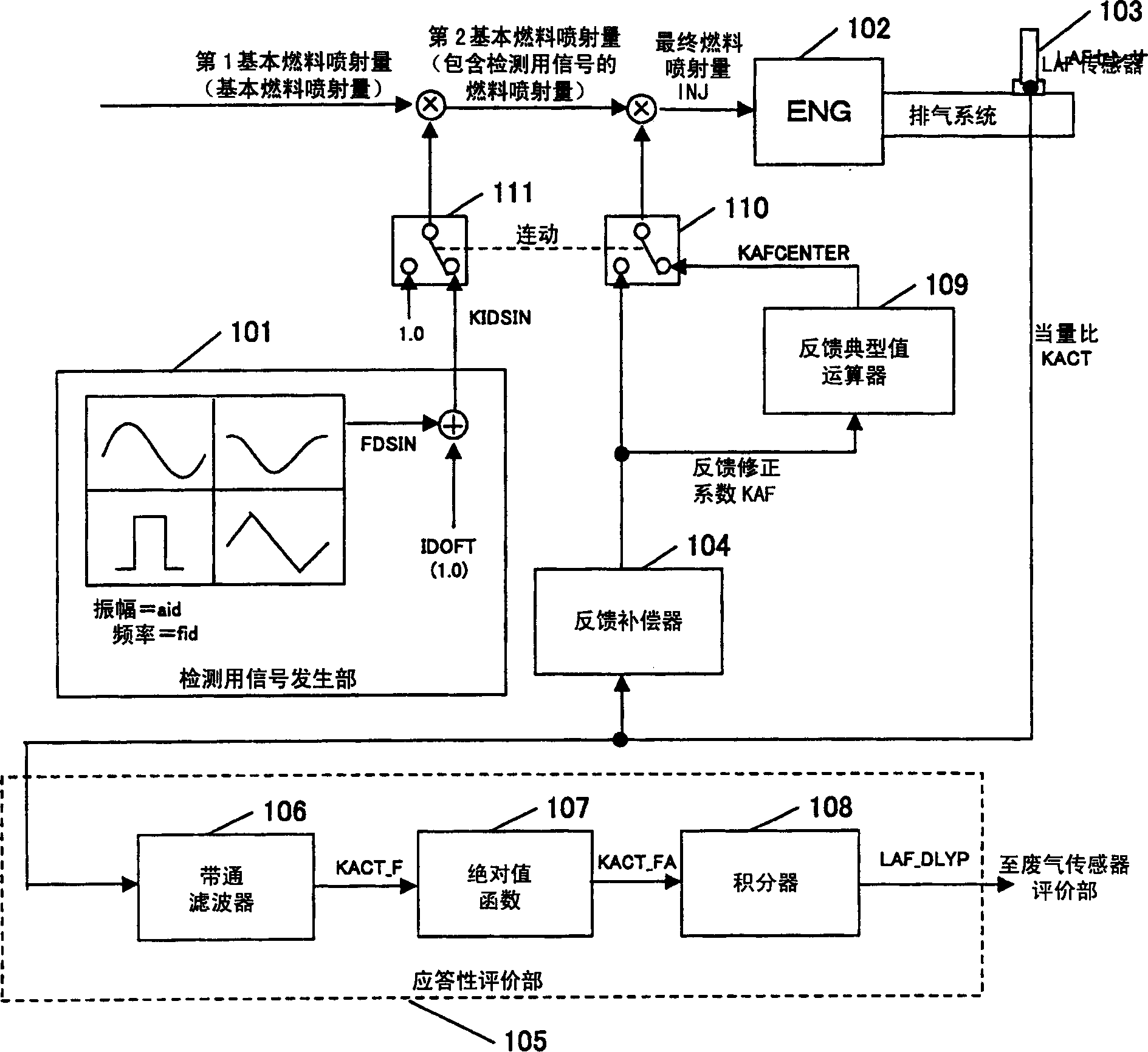
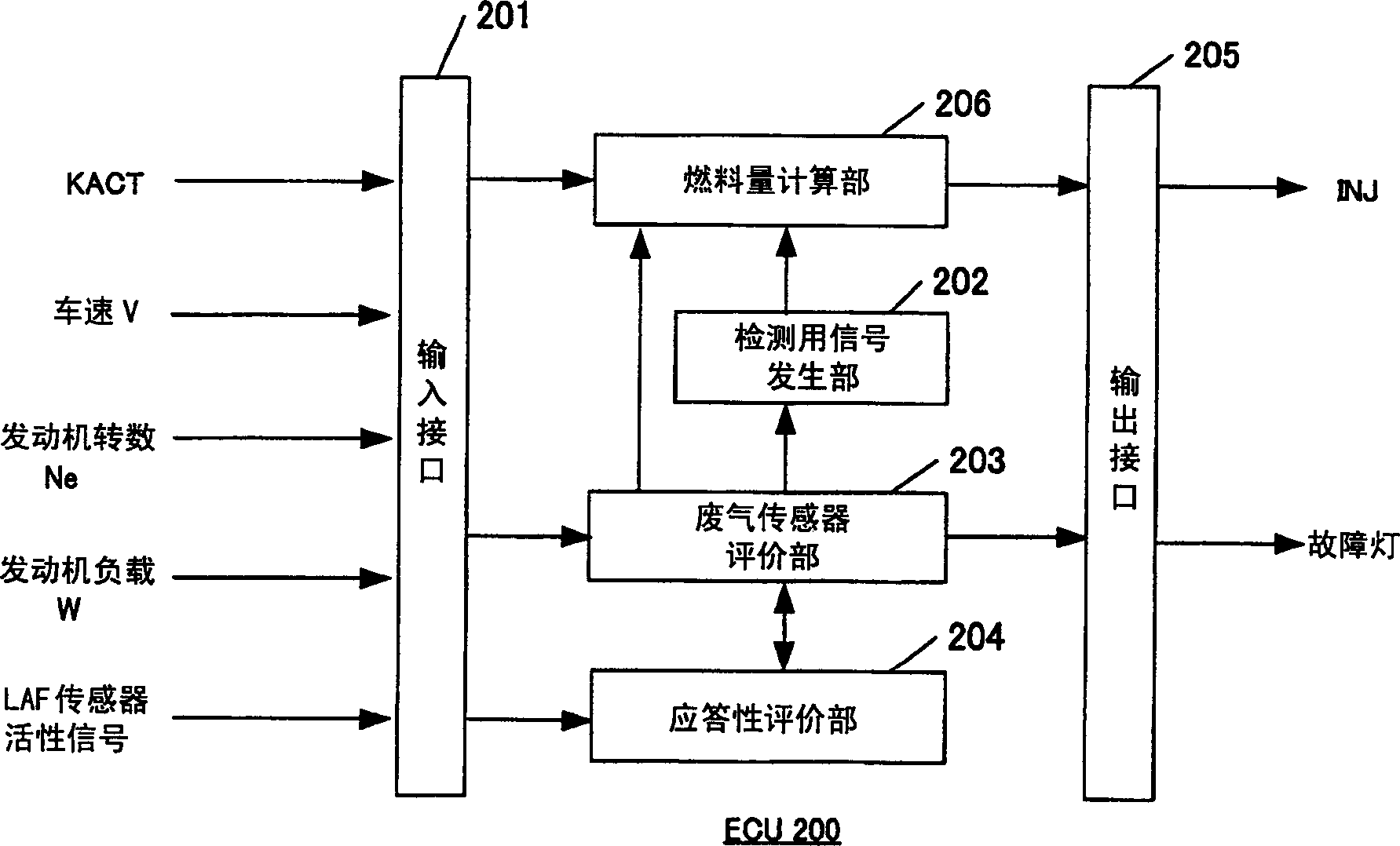
[0028] refer to Figure 1 ~ Figure 2 , describing each function block. figure 1 It is a block diagram showing the overall structure for explaining the concept of the present invention.

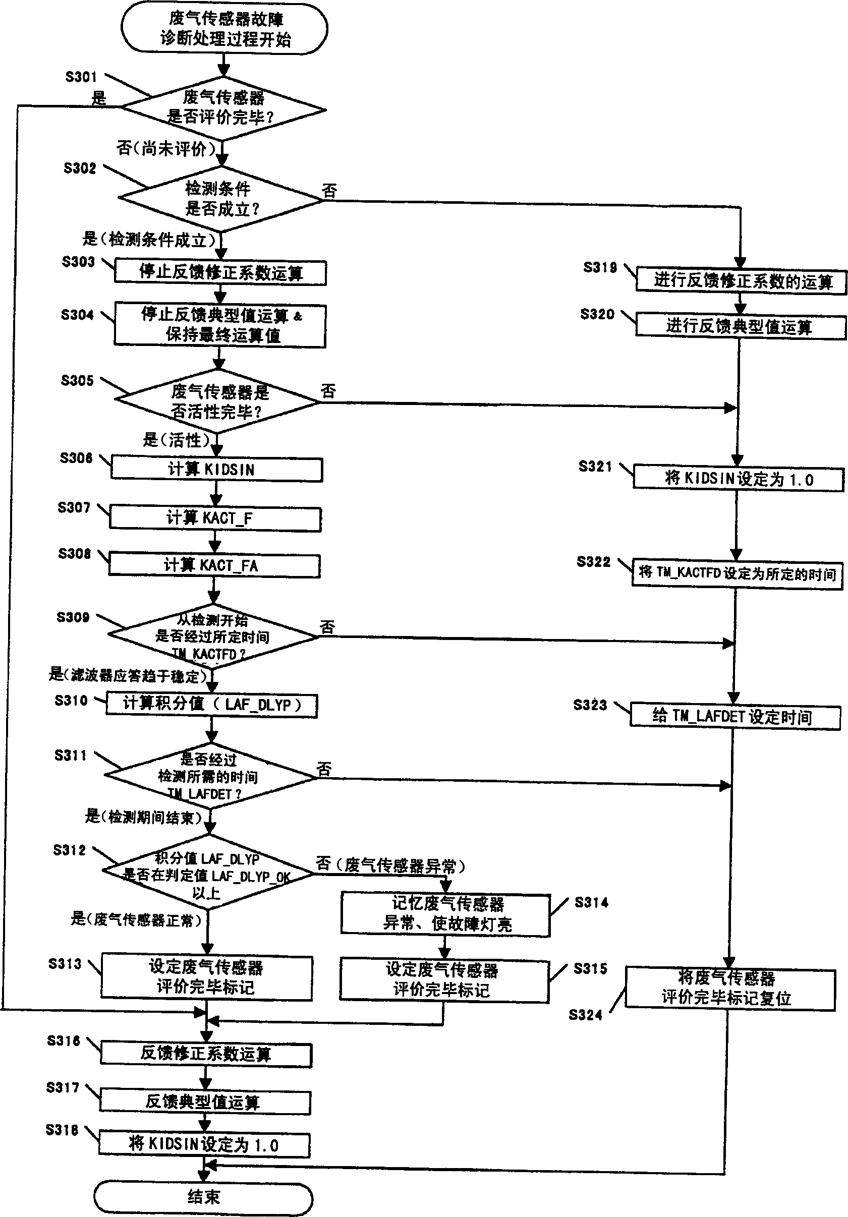
[0029] The detection signal generator 101 has a function of generating a predetermined detection signal KIDSIN obtained by superimposing a trigonometric function wave FDSIN or the like on an offset value IDOFT. Responsiveness evaluation unit 105 has equivalence ratio KACT, which is the output from wide-area air-fuel ratio sensor (hereinafter referred to as "LAF sensor") 103, which is band-pass filtered, and converts this value to an absolute value, and further converts the converted value at a predetermined value. It is a function to integrate during the period and send it to the exhaust gas sensor evaluation unit. The exhaust gas sensor evaluation unit has a function of judging a deterioration failure of the exhaust gas sensor based on these value...


PUM


Abstract

The present invention relates to a deterioration fault diagnosis device for an exhaust gas sensor that generates an output corresponding to an exhaust gas component of an internal combustion engine. The signal generation unit for detecting the injection quantity; obtain the typical feedback value based on the feedback correction coefficient, multiply the typical feedback value by the basic fuel injection quantity including the detection signal, and obtain the typical feedback of the final fuel injection quantity input to the internal combustion engine A value calculation unit; an exhaust gas sensor evaluation unit that extracts a frequency response corresponding to a detection signal from the output of the exhaust gas sensor for the final fuel injection amount of the internal combustion engine, and judges the state of the exhaust gas sensor based on the frequency response. It is possible to provide a failure diagnosis device for an exhaust gas sensor that improves the detection accuracy of a deterioration failure of the exhaust gas sensor and suppresses an increase in exhaust gas components during detection.

Description

technical field [0001] The invention relates to a device for diagnosing a deterioration fault of an exhaust gas sensor arranged in an exhaust pipeline of an internal combustion engine. Background technique [0002] An exhaust gas sensor is usually installed in the exhaust line of the internal combustion engine of a vehicle in order to measure the components of the exhaust gas. The exhaust gas sensor outputs the air-fuel ratio in the exhaust gas, and the control device of the internal combustion engine controls the air-fuel ratio of fuel supplied to the internal combustion engine based on the output value. Therefore, when the exhaust gas sensor has a deterioration failure and cannot provide a sensor output reflecting the correct air-fuel ratio, the control device cannot perform correct air-fuel ratio control on the internal combustion engine. [0003] Various techniques have been proposed as methods for measuring such deterioration failures of exhaust gas sensors. Patent Do...

Claims


Application Information

Patent Timeline
Patent Type & Authority Applications(China)
IPC IPC(8): F02D45/00F01N3/00F01N3/20F02D41/14
CPCF02D41/1454F02D41/1456F02D41/1495
Inventor 牧秀隆北川浩津田将岐
Owner HONDA MOTOR CO LTD
Features
  • Generate Ideas
  • Intellectual Property
  • Life Sciences
  • Materials
  • Tech Scout
  • Unparalleled Data Quality
  • Higher Quality Content
  • 60% Fewer Hallucinations
Learn More