Hydraulic commutation clutch and multifunctional tractor employing the same

A clutch and hydraulic technology, applied in the field of clutches, can solve problems such as short service life, oil leakage in the system, and many assembly links

Inactive Publication Date: 2005-03-16
YUCHAI ENG MACHINERY
View PDF0 Cites 1 Cited by
  • Summary
  • Abstract
  • Description
  • Claims
  • Application Information

AI Technical Summary

Problems solved by technology

[0005] ①The shifting oil pipe is too long, and its two ends are respectively connected with the transition joint 10 and the distribution sleeve 9 by an interface, which is difficult to adjust and install during assembly, and the sealing ring at the interface is prone to oil leakage during operation
[0006] ②In order to make the distribution sleeve 9 have a certain degree of adjustment during assembly, so as to be aligned with the port of the oil pipe for shifting gears, the distribution sleeve must be fitted on the front cover of the clutch in a floating manner. This structure makes the distribution sleeve 9 and the drive shaft 1 There will always be greater wear and tear between them during work, resulting in failure of the seal between the drive shaft 1 and the distribution sleeve 9
[0007] ③The oil distribution passage of the drive shaft 1 is provided with a distribution pipe 17, and the oil distribution passage and the distribution pipe 17 are sealed with an O-ring 13. This structure is difficult to process and assemble, and the O-ring is easy to cut during assembly. 13. Make it invalid, cause oil leakage in the system, make the working pressure insufficient or no working pressure at all, and the machine cannot work normally
[0009] ① Poor matching accuracy between cylinder 2 and piston 6
[0011] ③ The seal between the cylinder body 2 and the piston is unreliable by relying on the O-ring 7
[0012] 3) The rear clutch gear 3 and the driven shaft 4 rely on spline assembly for transmission. There are many assembly links, the structure is complex, and the working stability is poor. Moreover, this structure makes the distance between the two assembly bearings 5 ​​of the driven shaft 4 only 10mm. The stability of the high-speed rotation of the driving shaft 1 and the driven shaft 4 is poor
[0013] 4) The O-ring seal between the drive shaft 1 and the piston 6 makes the friction between the drive shaft 1 and the piston 6 too large, so more return springs 8 are required (generally 30 small springs are required), so the structure Complex, many assembly links
[0014] 5) The clutch housing and the engine housing are connected by positioning on one side of the two pins, so that the concentricity between the clutch driving shaft and the engine output shaft is poor, the stability and reliability of the movement are poor, and the service life is short

Method used


Image

  • Hydraulic commutation clutch and multifunctional tractor employing the same
  • Hydraulic commutation clutch and multifunctional tractor employing the same
  • Hydraulic commutation clutch and multifunctional tractor employing the same

Examples


Embodiment Construction

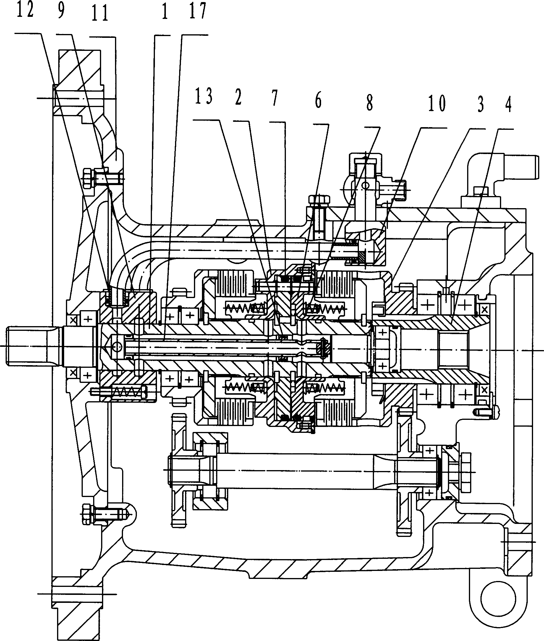
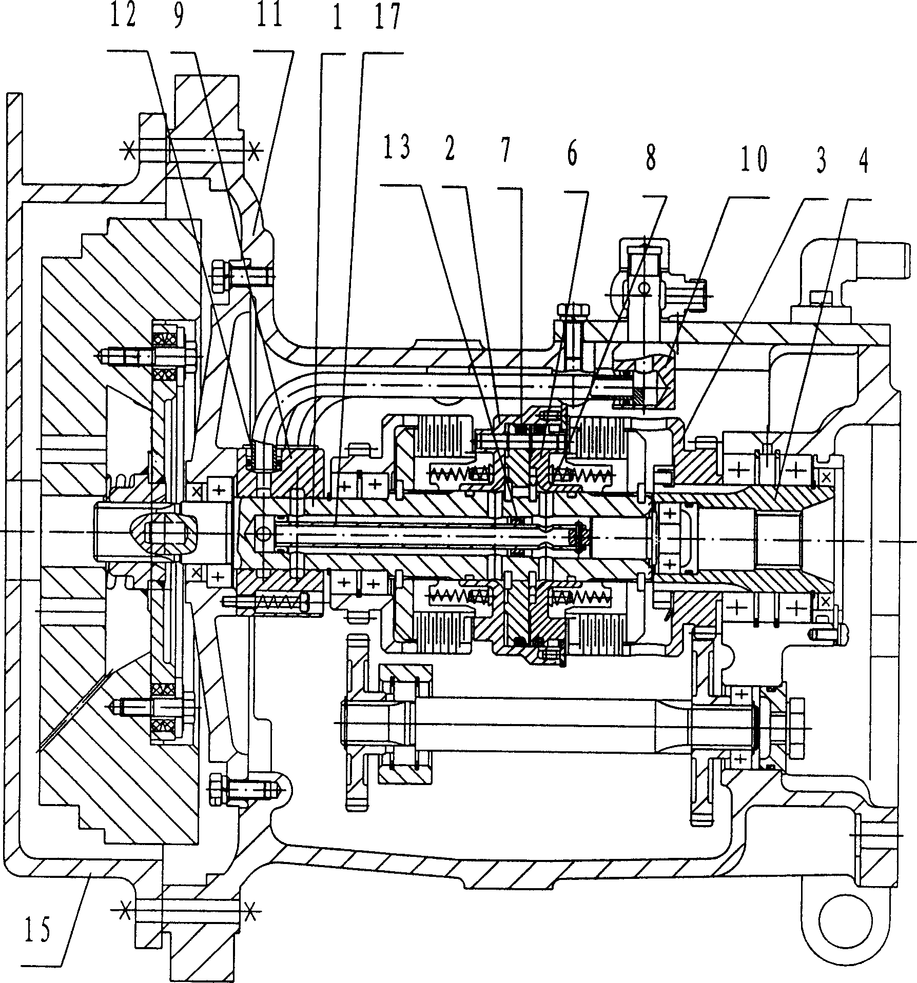
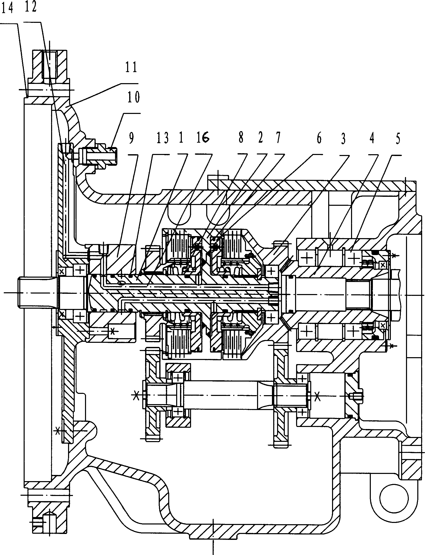
[0039] exist image 3 In the illustrated embodiment, the hydraulic reversing clutch includes a housing 11 and front and rear end covers, the driving shaft 1 and the driven shaft 4 are fitted on the front and rear end covers through the assembly bearing 5, and the front and rear clutches are assembled On the driving shaft 1, the working oil cylinder 2 is fixedly connected with the driving shaft 1, the rear clutch gear 3 is connected with the driven shaft 4, and the distribution sleeve 9 is set outside the driving shaft 1 and fixedly connected to the front end cover with bolts. The casing 11 is provided with two transition joints 10 for connecting with external pipelines, and the two transition joints 10 are respectively connected to one end of the two shifting oil passages 12 arranged in the casing 11, and the shifting oil passages 12 can be existing There is any structure in the clutch, such as two suspended gear oil pipes, but in order to make the structure of the hydraulic r...


PUM


Abstract

This invention is related to a fluid commutating clutch. Its oil route is: two transitional tie-ins on the shell-two counterpart oil routes-two independent oil routes of the initiative axletree-the chamber of oil jar of the front and the back clutches; the cover of the counterpart route is fixed on the front end, the oil jar is connected with the initiative axletree. This clutch has simple structure and equipping process, the oil route is hermetic and reliable, the performance of operation is sound and the time of usage is long. This invention is related to the multi-functional tractor that uses the above clutch. The tractor not only has the strong points of this clutch, but also it is assembled more reasonably. The concentric degree of the initiative axletree of the fluid clutch and the output axletree of the motor is higher.

Description

(1) Technical field: [0001] The invention relates to a clutch, especially a hydraulic reversing clutch, and also relates to a multifunctional tractor using the clutch. (two) background technology: [0002] Existing hydraulic reversing clutches are generally designed for large-scale machines, so the structure is complex and the cost is high. However, in medium and small construction machinery, such as medium and small tractors (tractors with a power of 15 to 80 horsepower), Generally, mechanical clutches are used, and whether it is a normally engaged or a very engaged mechanical clutch, when shifting gears, shifting gears, or changing direction, you must first step on the main clutch, cut off the power of the engine, and then pass through the gearbox. To realize shifting, shifting and reversing, the mechanical clutch is laborious and cumbersome to operate, has low work efficiency, and wears quickly and has a short service life. For this reason, the applicant has designed a k...

Claims


Application Information

Patent Timeline
Patent Type & Authority Applications(China)
IPC IPC(8): B60K17/02F16D25/06
Inventor 王新友杨照刚周夏南
Owner YUCHAI ENG MACHINERY
Why Eureka
Try Eureka