Magnetism integration DC/DC conversion boosting type transmission ratio expander circuit and high booster circuit

A technology that expands the circuit and transmission ratio, and is applied in the direction of conversion equipment without intermediate conversion to AC, which can solve the problems of transformer stray parameters, which have a large influence on circuit operation and increase the difficulty of transformer design.

Inactive Publication Date: 2005-03-16
YANSHAN UNIV
View PDF0 Cites 10 Cited by
  • Summary
  • Abstract
  • Description
  • Claims
  • Application Information

AI Technical Summary

Problems solved by technology

However, in actual circuits, the duty cycle of the power switch is generally only about 0.9.
[0004] Improving the transmission ratio of a circuit with a transformer requires that the primary and secondary sides of the transformer have a higher turn ratio. When the operating voltage difference between the primary and secondary sides of the transformer is large, the primary side will work at low voltage and high current; while the secondary side Then it works in the state of high voltage and low current, which makes the design of the transformer more difficult, and the stray parameters of the transformer will have a relatively greater impact on the operation of the circuit.

Method used


Image

  • Magnetism integration DC/DC conversion boosting type transmission ratio expander circuit and high booster circuit
  • Magnetism integration DC/DC conversion boosting type transmission ratio expander circuit and high booster circuit
  • Magnetism integration DC/DC conversion boosting type transmission ratio expander circuit and high booster circuit

Examples


Embodiment 1

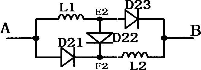
[0026] The step-up transmission ratio expansion circuit expands the number of stages n=2, and regards it as a two-port network AB, and the internal nodes are defined as E2 and F2 respectively (see figure 1 ), where A is the inductance L 1 and diode D 21 The intersection point of the anode; B is the inductance L 2 and diode D 23 Intersection of cathodes; internal node E2 is inductor L 1 and diode D 22 、D 23 The intersection point of the anode, the internal node F2 is the inductor L 2 and diode D21 、D 22 intersection point of the cathode.

Embodiment 2

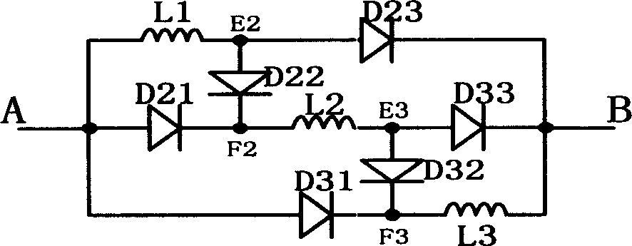
[0028] The step-up transmission ratio expansion circuit expands the number of stages n=3, and regards it as a two-port network AB, and the internal nodes are respectively defined as E2, E3 and F2, F3 (see figure 2 ), where A is the inductance L 1 and diode D 21 、D 31 The intersection point of the anode; B is the inductance L 3 and diode D 23 、D 33 Intersection of cathodes; internal node E2 is inductor L 1 and diode D 22 、D 23 The intersection point of the anode; E3 is the inductance L 2 and diode D 32 、D 33 Intersection of the anode; internal node F2 is the inductor L 2 and diode D 21 、D 22 The intersection point of the cathode; F3 is the inductance L 3 and diode D 31 、D 32 intersection point of the cathode.

Embodiment 3

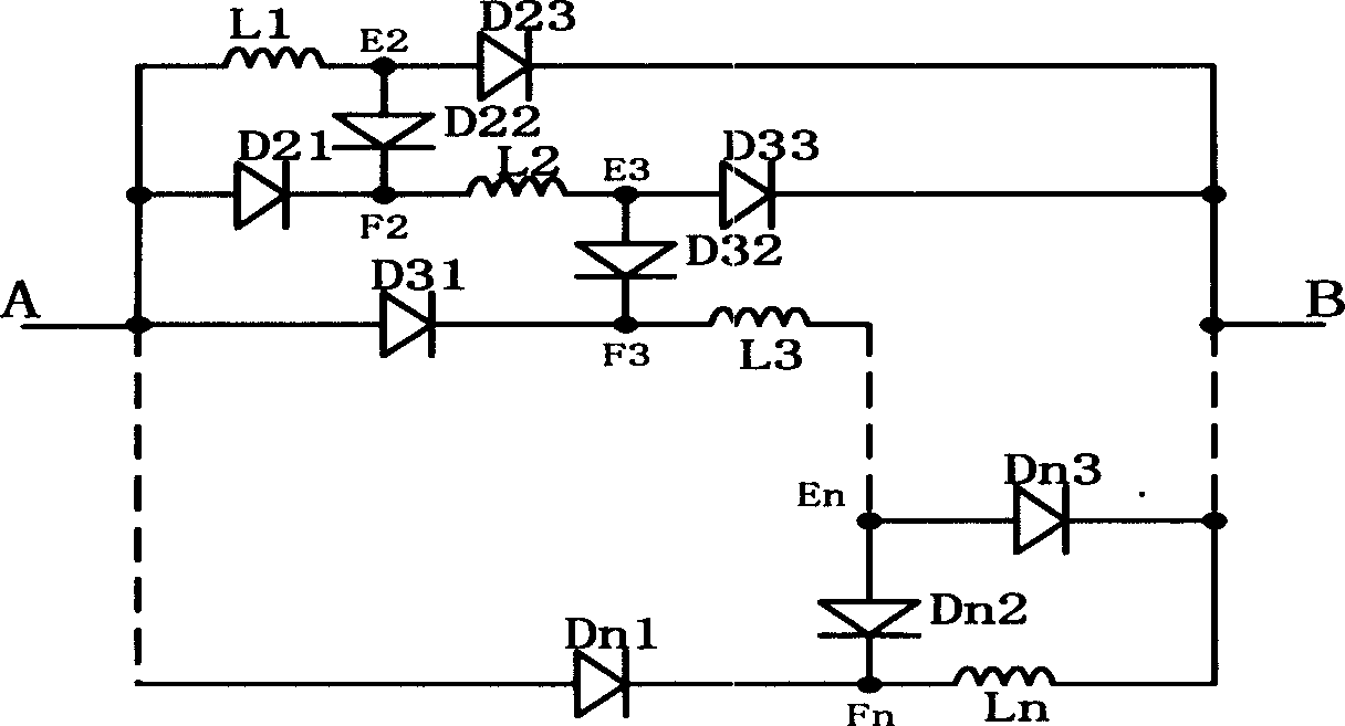
[0030] The expansion series of the step-up transmission ratio expansion circuit is n (2≤n≤500), and it is regarded as a two-port network AB, and the internal nodes are respectively defined as E2, E3...En and F2, F3...Fn (see image 3 ), where A is the inductance L 1 and diode D x1 The intersection point of the anode; B is the inductance L n and diode D x3 Intersection of cathodes; internal node E x is the inductance L x-1 , and diode D x2 、D x3 The intersection point of the anode, the internal node Fx is the inductance L x and diode D x1 and D x2 Intersection of cathodes (where x=2, 3...n).


PUM


Abstract

The invention is a magnetic integrated DC/DC conversion boost transmission ratio extension circuit and a high boost transmission ratio circuit, and as realizing the stage extension of a boost-type transmission ratio extension two-port network from stage n to n+1, the inductance and diode regularly increase by degrees, i.e. adding an inductance and three diodes can realize the extension from the stage n to n+1; the DC/DC conversion boost transmission ratio extension circuit with extended stage number n (2<=n<=500) is applied to a traditional boost converter, which composes a like-polarity high boost transmission ratio circuit, where the transmission ratio M=n/(1-D); and as the DC/DC conversion boost transmission ratio extension circuit with extended stage number n (2<=n<=500) is applied to a traditional buck-boost converter, which composes a reversed-polarity high boost transmission ratio circuit, where the transmission ratio M=-(nD)/ (1-D); it can realize the magnetic integration of many inductances in a boost transmission ratio extension circuit by adopting magnetic integrated multi-winding coupled inductance.

Description

technical field [0001] The invention relates to a DC / DC conversion step-up transmission ratio expansion circuit, which is composed of a linear inductance and a diode. Two types of step-up transmission ratio expansion circuits can be formed by using the step-up transmission ratio expansion circuit. Background technique [0002] At present, in the known DC / DC conversion technology, circuits capable of realizing step-up transmission include: Boost converter, Buck-Boost converter, Cuck converter, etc.; excitation, bridge, half-bridge and push-pull circuits, etc. [0003] In order to improve the step-up transmission ratio of the circuit (the transmission ratio is defined as the ratio of the average voltage Vo at the output terminal to the average voltage Vin at the input terminal, that is, M=Vo / Vin), the transformerless step-up circuit needs to increase the power as much as possible The duty ratio D of the tube (D is defined as the ratio of the switch conduction time Ton to the ...

Claims


Application Information

Patent Timeline
Patent Type & Authority Applications(China)
IPC IPC(8): H02M3/08
Inventor 邬伟扬孙孝峰金晓毅
Owner YANSHAN UNIV
Why Eureka
Try Eureka