High-voltage transformation ratio LLC resonant converter based on low-turn high-voltage transformation ratio planar transformer and integrated magnetic part

A planar transformer, high-voltage technology, applied in the direction of transformer/inductor coil/winding/connection, high-efficiency power electronic conversion, transformer/inductance parts, etc., can solve the problem of complex winding structure, large number of turns and layers, and efficiency low level problem

Pending Publication Date: 2021-09-03
杨玉岗
View PDF0 Cites 0 Cited by
  • Summary
  • Abstract
  • Description
  • Claims
  • Application Information

AI Technical Summary

Problems solved by technology

Due to the complex structure and low efficiency of the two-stage converter, the single-stage LLC resonant converter will become the future development trend. Or 380:12=32:1), even if a wide bandgap device such as gallium nitride is used, the switching frequency is increased to MHz, and the number of turns of the secondary winding of the transformer is reduced to only one turn, the primary winding still has many turns (such as 48 turns, 63 turns or 32 turns), resulting in a large number of turns and layers of PCB windings for high-frequency planar transformers, and a complex winding structure, which restricts the power supply system of the data center to reduce cost and height, improve efficiency and power density, and save energy. A critical bottleneck in energy

Method used


Image

  • High-voltage transformation ratio LLC resonant converter based on low-turn high-voltage transformation ratio planar transformer and integrated magnetic part
  • High-voltage transformation ratio LLC resonant converter based on low-turn high-voltage transformation ratio planar transformer and integrated magnetic part
  • High-voltage transformation ratio LLC resonant converter based on low-turn high-voltage transformation ratio planar transformer and integrated magnetic part

Examples


Embodiment 1

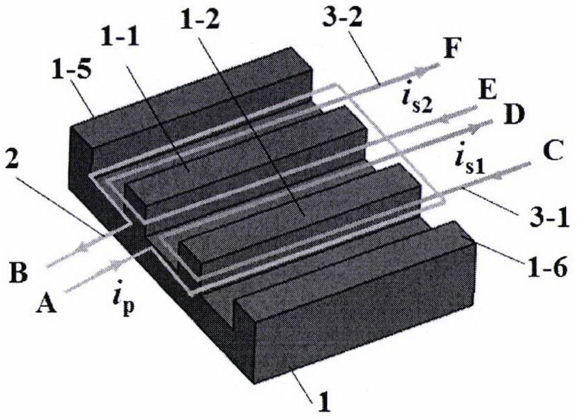
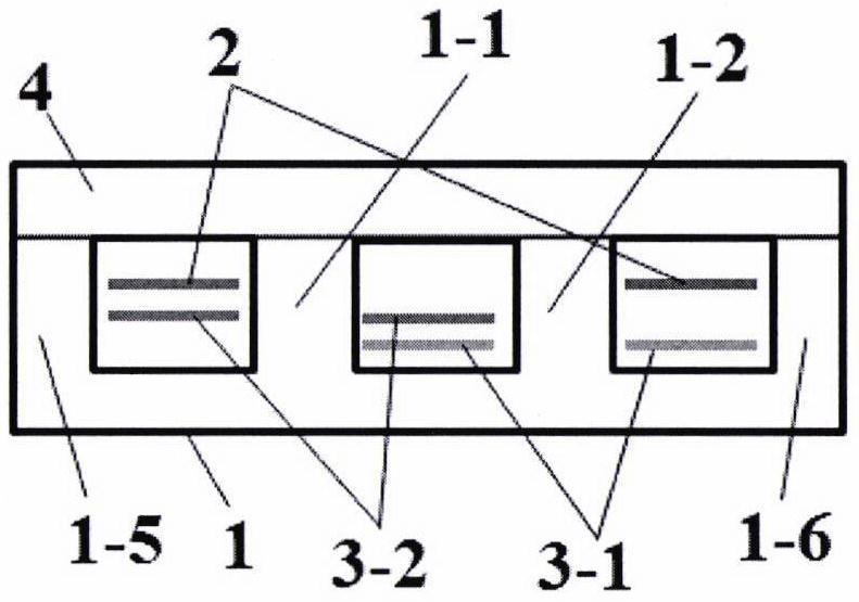
[0029] Refer to attached figure 1 , 2 , a planar transformer with low turns and high voltage ratio, including two iron cores and three windings; one of the iron cores is divided into two by the middle column of the traditional planar "E" type iron core, forming the same shape as the traditional planar "E" The side columns 1-5 and 1-6 of the E" type iron core are parallel to the two center columns 1-1 and 1-2, forming a plane shaped iron core 1, and the other iron core is a traditional planar "I" shaped iron core 4; one of the windings is the primary winding 2, all bypassing the plane The two central columns 1-1 and 1-2 of the shaped iron core 1; the other two windings are the secondary windings 3-1 and 3-2, the number of turns is equal, and they are respectively wound on the plane on the two center columns 1-1 and 1-2 of the shaped iron core 1; the plane "I" shaped iron core 4 covers the plane Above the shaped iron core 1, one of the planar transformer structures with l...

Embodiment 2

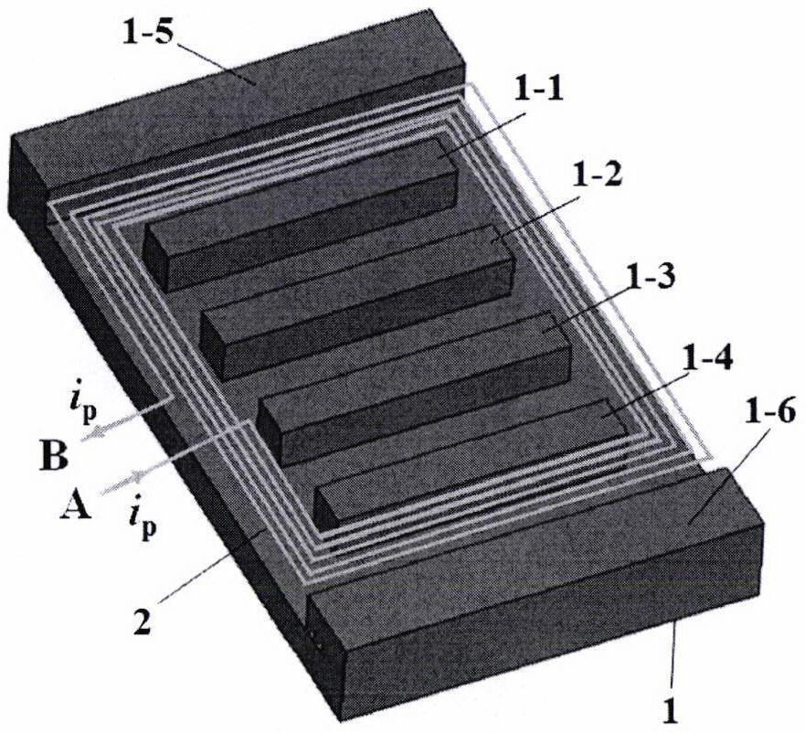
[0031] Refer to attached image 3 , 4 , a planar transformer with low turns and high voltage ratio, divides the central column of the traditional planar "E" core into four, forming four central columns 1-1, 1-2, 1-3 and 1-4 , forming a plane Shaped iron core 1, the four middle columns 1-1, 1-2, 1-3 and 1-4 are shorter than the two side columns 1-5 and 1-6 of the traditional planar "E" type iron core; a The primary winding 2 all bypasses the four iron core columns 1-1, 1-2, 1-3 and 1-4; the four secondary windings 3-1, 3-2, 3-3 and 3- The number of turns of 4 is equal, and is an odd number of turns, respectively wound on the four iron core middle columns 1-1, 1-2, 1-3 and 1-4, respectively from the four secondary side windings 3-1, 3- 2, 3-3 and 3-4 lead to the middle tap C 1 ,E 1 , G 1 、J 1 , the middle tap leads from the bottom of the transformer to the ends C, D, E, F, G, H, J, K of the secondary winding to form a secondary winding structure with odd turns and a midd...

Embodiment 3

[0036] Refer to attached Figure 5 , in the attached image 3 plane in Add a primary side leakage inductance magnetic column 1-7 on the shaped iron core 1, the length direction of the primary side leakage inductance magnetic column 1-7 is the same as that of four middle columns 1-1, 1-2, 1-3, 1-4 The length directions are perpendicular; the primary winding 2 also bypasses the magnetic column 1-7, but the four secondary windings 3-1, 3-2, 3-3, and 3-4 do not bypass the magnetic column 1-7; The number of turns of each secondary winding is an even number of turns, and all of them lead to the middle tap C 1 ,E 1 , G 1 、J 1 , the center tap is located on the same side of the ends C, D, E, F, G, H, J, K of the secondary windings 3-1, 3-2, 3-3, 3-4; forming a low number of turns One of the integrated magnetic parts structure of high voltage ratio planar transformer + primary side leakage inductance; due to the addition of primary side leakage inductance magnetic columns 1-7, t...


PUM


Abstract

The invention provides a high-voltage transformation ratio LLC resonant converter based on a low-turn high-voltage transformation ratio planar transformer and an integrated magnetic part. The converter comprises two iron cores and three windings; one iron core divides a middle column of the plane E-shaped iron core into two parts to form two middle columns to form a plane-shaped iron core, and the other iron core is in a plane I shape; one winding is a primary winding and completely bypasses the two middle columns; the other two windings are secondary windings, have the same number of turns and are respectively wound on the two middle columns; and the plane I-shaped iron core covers the plane iron core. The converter has the beneficial effects that: high-voltage transformation ratio, large-current output and magnetic integration of the transformer are achieved with the minimum number of turns of the primary winding and the secondary winding, the high-voltage transformation ratio LLC resonant converter is used for a data center power supply system, new energy power generation and an electric automobile, the capacity is enlarged, the size is reduced, cost is reduced, efficiency is improved, and energy is saved.

Description

technical field [0001] The invention relates to the technical field of power electronics applications, in particular to a high-voltage ratio LLC resonant converter based on a low-turn, high-voltage ratio planar transformer and integrated magnetic parts. Background technique [0002] According to Moore's Law, when the price remains constant, the number of semiconductor elements that can be accommodated on a single microprocessor (CPU) chip integrated circuit doubles approximately every 18-24 months, and the performance also doubles . As the heating problem of single-core CPU is getting more and more serious, in order to facilitate heat management, Intel has designed a multi-core CPU structure, such as the XeonW-3175 CPU chip, which integrates 28 cores on one CPU chip, and this chip needs to consume 2V× 350A electric power. In addition, in recent years, the development of GPU (Image Processor) technology has surpassed Moore's Law, and 600 cores are integrated on a single chi...

Claims


Application Information

Patent Timeline
Patent Type & Authority Applications(China)
IPC IPC(8): H01F27/245H01F27/30H02M3/335
CPCH01F27/245H01F27/306H02M3/33576Y02B70/10
Inventor 杨玉岗
Owner 杨玉岗
Why Eureka
Try Eureka