Error decoding circuit, data bus control method and data bus system

A decoding circuit and data bus technology, applied in the field of data processing, can solve the problems of long processing time and large error correction circuit scale, and achieve the effects of high-speed processing, high-speed data bus cycle, and simple structure

Inactive Publication Date: 2005-03-16
FANUC LTD
View PDF1 Cites 4 Cited by
  • Summary
  • Abstract
  • Description
  • Claims
  • Application Information

AI Technical Summary

Problems solved by technology

[0024] In addition, in the existing structure using a CRC check circuit, since the CRC code is used, it is necessary to perform a CRC check on the error-corrected data, so not only the CRC check for detecting errors in the received data is required Circuit (CRC checking circuit 12f among Fig. 8), also needs the CRC checking circuit (CRC checking circuit 12b among Fig. 8) that the corrected data is used, has the problem that double needs CRC checking circuit
[0025] In addition, since the error correction code is also required for the CRC code, in addition to the problem that the scale of the error correction circuit becomes larger, there is also a problem that the processing time becomes longer.

Method used


Image

  • Error decoding circuit, data bus control method and data bus system
  • Error decoding circuit, data bus control method and data bus system
  • Error decoding circuit, data bus control method and data bus system

Examples


Embodiment Construction

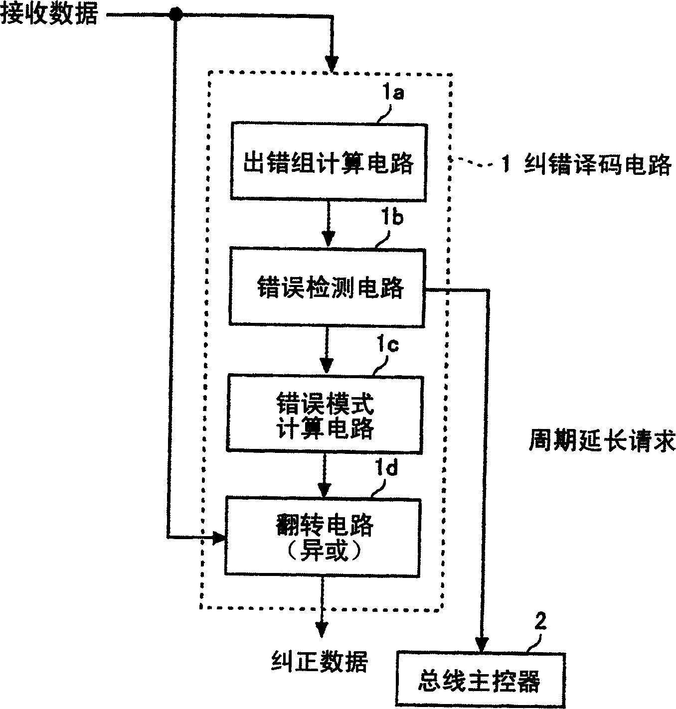
[0053] figure 1 It is a figure for explaining the outline|summary of the error correction decoding circuit of this invention. figure 1 The shown error correction decoding circuit 1 has an error group calculation circuit 1a that inputs received data and calculates the error group, an error detection circuit 1b that detects an error based on the calculated error group, and calculates an error pattern based on the error group when an error is detected. An error pattern calculation circuit 1c, and an inversion circuit 1d for error-correcting received data based on the calculated error pattern.

[0054] The error detection circuit 1b outputs a bus cycle extension request signal to the bus master 2 when it determines that there is an error in the received data based on the detection result.

[0055] In addition, received data is data received via a transmission path by adding a check bit to input data using an encoding circuit not shown. The transmission path is not limited to a...


PUM


Abstract

An error decoding circuit comprises a syndrome computing circuit for computing a syndrome on a receive data, an error detecting circuit for detecting an error based on the syndrome, an error pattern computing circuit for computing an error pattern based on the syndrome, and an inverting circuit for performing an error correction of a receive data based on the computed error pattern. Only when there is an error in the receive data, based on the detection result of the error detecting circuit, a request signal for extension of a bus cycle is outputted to a bus master. On the other hand, if there is no error in the receive data, an inputted data is outputted to a data bus without correction. By so doing, the high speed operation of the data bus is executed.

Description

technical field [0001] The present invention relates to data processing for obtaining corrected data by performing error correction processing on received data, to an error correction decoding circuit for decoding received data, a control method for connecting a data bus connected to the error correction decoding circuit, and a control method including the data bus system. Background technique [0002] A method of using an error-correcting code to correct an error in data is known. Here, using Figure 6 A brief description of error correction using error correcting codes. [0003] Figure 6 , the input data is encoded by the encoding circuit 10. The encoding circuit 10 forms check bits based on, for example, a parity check matrix described later, adds the check bits to input data, and generates transmission data. [0004] The transmission data is sent to the transmission path 11, and the transmission path 11 delivers the reception data to the communication destination. T...

Claims


Application Information

Patent Timeline
Patent Type & Authority Applications(China)
IPC IPC(8): H03M13/15G06F11/00G06F11/07G06F11/10G06F13/00H03M13/00H04L1/00
CPCH03M13/151G06F11/0745H03M13/1575G06F11/0793
Inventor 青山一成相泽安晴小槙邦孝
Owner FANUC LTD
Why Eureka
Try Eureka