

Soil divider of ditching machine
A trencher and soil divider technology, applied in the direction of excavation/covering of trenches, applications, planting methods, etc., can solve the problem that the uniformity of soil throwing and the distance of the covering surface cannot meet the agronomic requirements, and the soil divider cannot be adjusted to fix the elevation angle. Agronomy, difficult to use the whole board and other problems, to achieve the effect of good soil covering, low cost, satisfactory uniformity and distance
- Summary
- Abstract
- Description
- Claims
- Application Information
AI Technical Summary
Problems solved by technology
Method used
Image

Examples
Embodiment 1
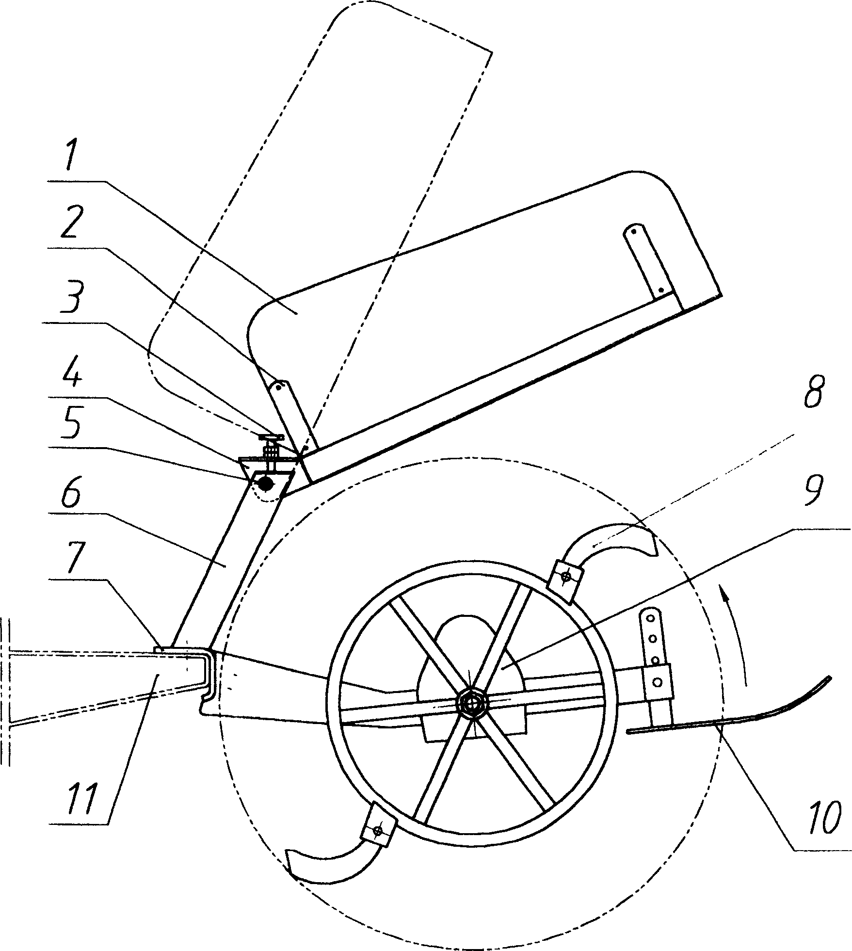
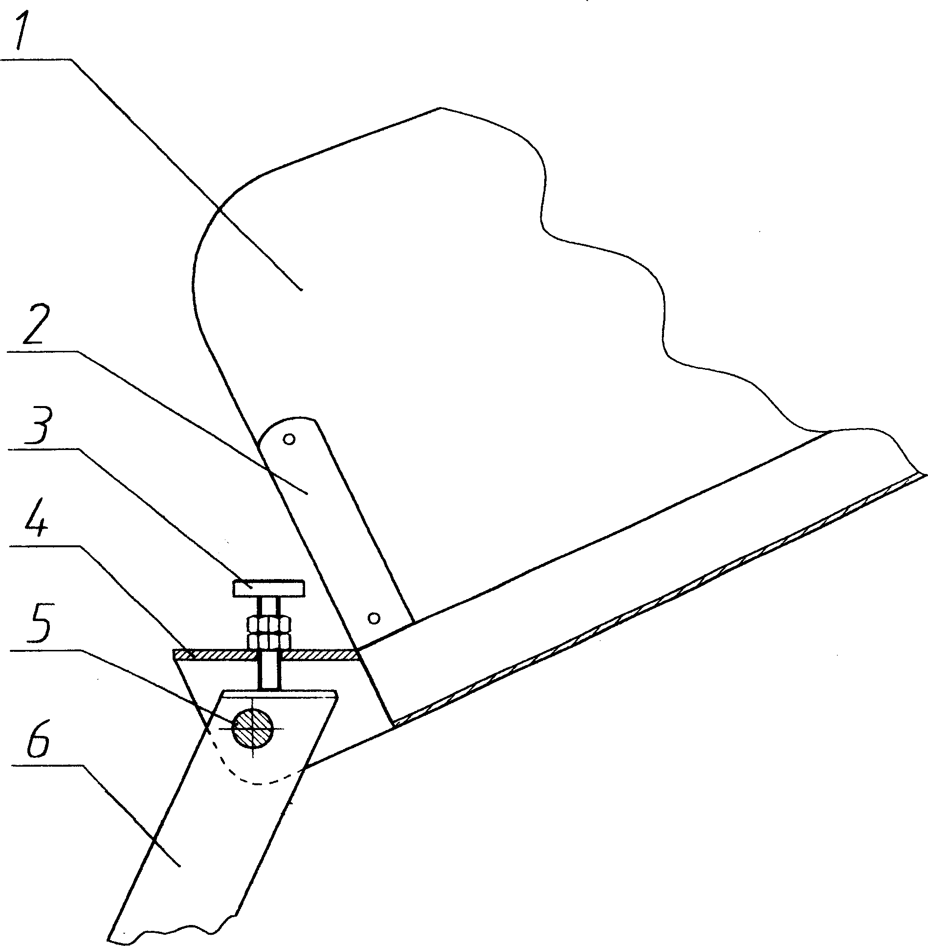
[0021] Example 1, figure 1 Among them, the ditching machine composed of frame 7, cutter head 8, gear box 9, depth stopper 10, etc. is assembled on the front end of walking tractor frame 11; 1 is made of one piece of material, and the lower edge line of the sub-soil board 1 is a straight line. In order to improve the strength, a reinforced skeleton 2 can also be lined on the sub-soil board 1 (see figure 2 , 3); a support column 6 is arranged on the frame 7 of the ditching machine, and the top of the support column 6 is made into a plug; On the top of the supporting column 6, the locking bolt 5 is horizontally penetrated as the connection and torsion shaft; the clamp seat 4 is provided with an adjusting screw 3 for adjusting the installation angle of the dividing soil plate, and the dividing screw 3 can be adjusted by turning the adjusting screw 3. The elevation angle of earthenware, the bottom of earthenware can be close to cutterhead 8 when the lowest time division, and ear...
Embodiment 2
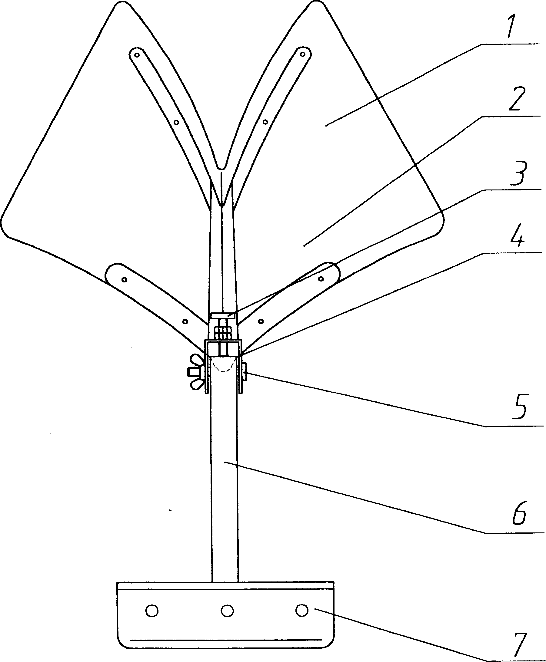
[0022] Example 2, Figure 4 Yet another structure of the hinged locking mechanism represented in Embodiment 2 is provided: a support column 6 is set on the frame 7 of the ditching machine, and the top of the support column 6 is made into an insert block; A clip seat 4, the clip seat 4 is clamped on the top of the support column 6, and is penetrated by the locking bolt 5 as a coupling and torsion shaft; and figure 1 , 2 1. The difference from the embodiment in 3 is that the clamping seat 4 is provided with several adjustment holes which are matched with the pin shaft holes on the support column 6 for adjusting the installation angle of the soil divider, and the pin shafts are inserted in the pin shaft holes 3. To adjust the elevation angle of the soil divider, first loosen the locking bolt 5, then pull out the pin shaft 3, turn the soil divider upwards or downwards, adjust to a suitable position, insert the pin shaft 3, and then tighten the locking bolt 5 to achieve Implemen...
Embodiment 3
[0023] Example 3, Figure 5 An embodiment of setting the hinge locking mechanism on the frame base is provided: the clip base 4 is connected with the ditching machine frame base 7, and several pin holes on the clamp base 4 and the support column 6 are provided Matching adjustment holes for adjusting the installation angle of the soil divider, the upper end of the support column 6 is connected to the skeleton 2 on the soil divider 1; The pin shaft 3 is positioned; loosen the locking bolt 5, extract the pin shaft 3, turn the soil divider upward or downward, adjust to a suitable position, insert the pin shaft 3, and then tighten the locking bolt 5 to achieve the implementation purpose.
[0024] According to the characteristics that the amount of soil thrown at the front of the cutter head is large, and the flow direction of the clod is forward and upward, while the amount of soil thrown at the rear is small, and the direction of the flow of the clod is backward. In order to prote...
PUM
 Abstract
Description
Claims
Application Information