Integrated suspension bed inorganic mambrane reactor
An inorganic membrane, suspended bed technology, applied in chemical instruments and methods, chemical/physical processes, etc., can solve the problems of reducing the effective space of the reactor, affecting the membrane permeation efficiency, increasing investment costs, etc., to improve the membrane separation performance, reduce Equipment investment and operating costs, the effect of preventing deposition
- Summary
- Abstract
- Description
- Claims
- Application Information
AI Technical Summary
Problems solved by technology
Method used
Image
Examples
example 1
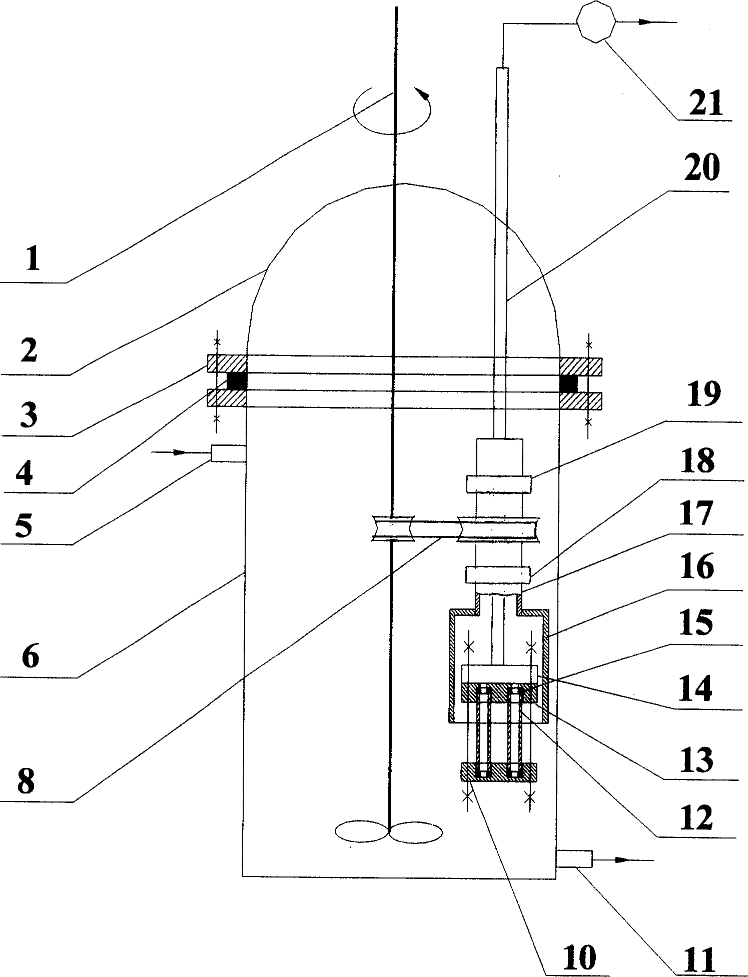
[0012] figure 1 In the example, the integrated suspended bed inorganic membrane reactor has a reactor 6, a top cover 2, and a sealing gasket 4 is added therebetween. The reactor is provided with a material inlet pipe 5, a material outlet pipe 11, and a filtrate outlet pipe connected to a vacuum pump 21. 20. A set of membrane modules consisting of two (or more) inorganic membrane tubes 12 and their supporting frame is arranged in the kettle. The membrane tube supporting frame is formed by connecting upper and lower metal supporting plates 10 and 13 through bolts. The two ends of the membrane tube 12 are padded with graphite gaskets 15, which are fixed through the socket holes of the metal support plates 10 and 13. The lower end of the inorganic membrane tube is sealed by the circular metal plate 10, and the upper end is connected with the circular liquid collecting container 14. Pass. The circular collecting container 14 is connected with the filtrate outlet pipe 20 . The fil...
example 2
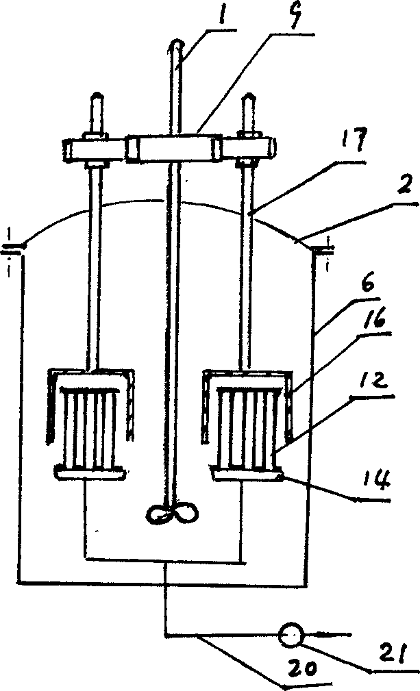
[0015] figure 2 In the example, two groups of inorganic membrane modules are arranged in the reaction kettle 6, each group contains several membrane tubes 12, the upper end of the membrane tube is closed, and the lower end communicates with the liquid collecting container 14, and each liquid collecting container 14 is connected with the filtrate outlet pipe 20 ; In this example, the shafts 17 of the two turbulent flow promoters 16 are connected with the agitator 1 to engage the gear set 9 . Mesh gear set can be located outside the top cover, also can be located in the reactor 6.
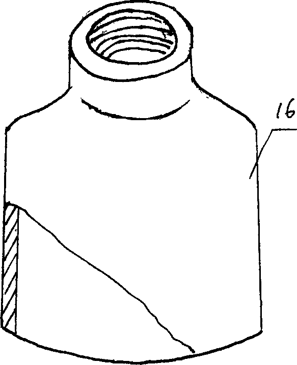
[0016] image 3 Indicates that the upper end of the cylindrical turbulence promoter 16 is provided with an internal thread port, through which it is connected with the rotating shaft 17
[0017] Figure 4 Represents a helical turbulence promoter 16, whose upper end can be connected with the rotating shaft 17 by welding.
Embodiment 2
[0019] Membrane flux test 1
[0020] On this device, the membrane filtration enhancement effect was investigated for the titanium-silicon molecular sieve catalyst suspension with an average particle size of 428nm. The basic filtration conditions are: an alumina ceramic membrane with an average pore size of 0.5 μm, a transmembrane pressure of 0.2 atm, a suspension temperature of 20 °C, and a suspension concentration of 5 g L -1 . The results show that for the titanium-silicon molecular sieve catalyst suspension, the membrane flux when the turbulent flow promoter rotates at 400 rpm is 2.5 times the membrane flux when the turbulence promoter rotates at 50 rpm.
[0021] Membrane flux test 2
[0022] On this device, the membrane filtration enhancement effect was investigated for the zirconia suspension with an average particle size of 475nm. The basic filtration conditions are: an alumina ceramic membrane with an average pore size of 0.5 μm, a transmembrane pressure of 0.2 atm, ...
PUM
 Abstract
Description
Claims
Application Information
 - R&D
- Intellectual Property
- Life Sciences
- Materials
- Tech Scout
- Unparalleled Data Quality
- Higher Quality Content
- 60% Fewer Hallucinations
Browse by: Latest US Patents, China's latest patents, Technical Efficacy Thesaurus, Application Domain, Technology Topic, Popular Technical Reports.
© 2025 PatSnap. All rights reserved.Legal|Privacy policy|Modern Slavery Act Transparency Statement|Sitemap|About US| Contact US: help@patsnap.com


