

Sintering device of loose body optical fiber prefabricated rod
A technology of optical fiber preform and sintering device, which is applied in the direction of manufacturing tools, glass molding, glass manufacturing equipment, etc., can solve the problems of uneven length direction, failure of heating element, and misalignment, etc., so as to reduce the increase of loss and ensure Uniformity, concentricity improvement effect
- Summary
- Abstract
- Description
- Claims
- Application Information
AI Technical Summary
Problems solved by technology
Method used
Image

Examples
specific example 1
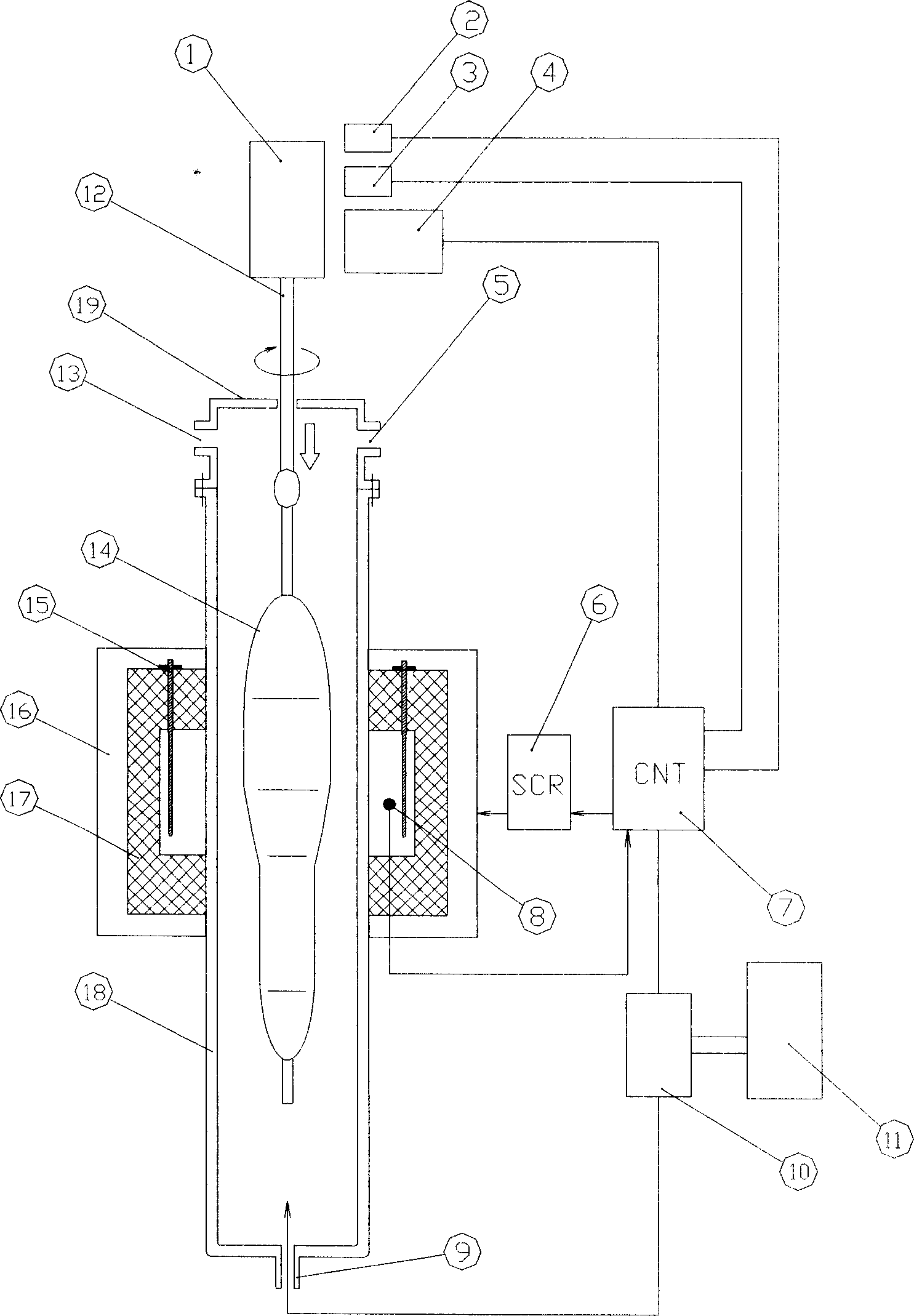
[0044]The soot preform 14 after external deposition is vertically suspended on the hanging rod 12 of the sintering tower, and the soot preform is slowly put into the sintering tube 18 through the lifting and translation of the servo motor 1; into the sintering tube, and placed on the sintering area of the heating device, cover the upper part of the sintering tube with a cover 19 to form a relatively airtight sintering atmosphere; the control device 7 controls the heating element 15 through the electric heater driving part When the temperature rises to 1100°C, gas such as 0.35 splm chlorine and 35 slpm helium is introduced into the sintered tube from the gas supply part 11 for dehydration. The proportion of gas is controlled at 1%; the dehydration time is 1 hour, and after the end, the electric heater driving part 6 controls the heating element 15 to raise the furnace temperature to 1500 °C; the control device 7 passes the position sensing device 3 and the speed sensing device...
specific example 2
[0046] The soot preform 14 after external deposition is vertically suspended on the hanging rod 12 of the sintering tower, and the soot preform is slowly put into the sintering tube 18 through the lifting and translation of the servo motor 1; into the sintering tube, and placed on the sintering area of the heating device, cover the upper part of the sintering tube with a cover 19 to form a relatively airtight sintering atmosphere; the control device 7 controls the heating element 15 through the electric heater driving part When the temperature rises to 1200°C, gas such as 0.6 splm chlorine and 25 slpm helium is introduced into the sintered tube from the gas supply part 11 for dehydration. The proportion of gas is controlled at 2.3%; the dehydration time is 0.75 hours, and after the end, the electric heater driving part 6 controls the heating element 15 to raise the furnace temperature to 1550 °C; the control device 7 passes the position sensing device 3 and the speed sensing ...
specific example 3
[0048] The soot preform 14 after external deposition is vertically suspended on the hanging rod 12 of the sintering tower, and the soot preform is slowly put into the sintering tube 18 through the lifting and translation of the servo motor 1; into the sintering tube, and placed on the sintering area of the heating device, cover the upper part of the sintering tube with a cover 19 to form a relatively airtight sintering atmosphere; the control device 7 controls the heating element 15 through the electric heater driving part When the temperature rises to 1200°C, gas such as 10 splm chlorine and 20 slpm helium is introduced into the sintered tube from the gas supply part 11 for dehydration. The ratio of dehydration is controlled at 4.7%; the dehydration time is 0.5 hours, and after the end, the electric heater driving part 6 controls the heating element 15 to raise the furnace temperature to 1550 ° C; the control device 7 is controlled by the position sensing device 3 and the sp...
PUM
 Abstract
Description
Claims
Application Information