Rotating engine

A rotary engine and rotor technology, applied to rotary piston engines, rotary or oscillating piston engines, combustion engines, etc., can solve the problems of increased difficulty in processing and manufacturing, friction and seizure, etc., and achieve low cost of use and easy operation The effect of convenience and simple structure

Inactive Publication Date: 2005-03-23
于贵
View PDF2 Cites 3 Cited by
  • Summary
  • Abstract
  • Description
  • Claims
  • Application Information

AI Technical Summary

Problems solved by technology

The intake and exhaust ports of the rotary engine do not need one-way valves, but there are rollers on each slide plate and control grooves on the inner side of the stator end cover, which makes the processing and manufacturing more difficult, and is also prone to wear and seizure

Method used


Image

  • Rotating engine
  • Rotating engine
  • Rotating engine

Examples


Embodiment 1

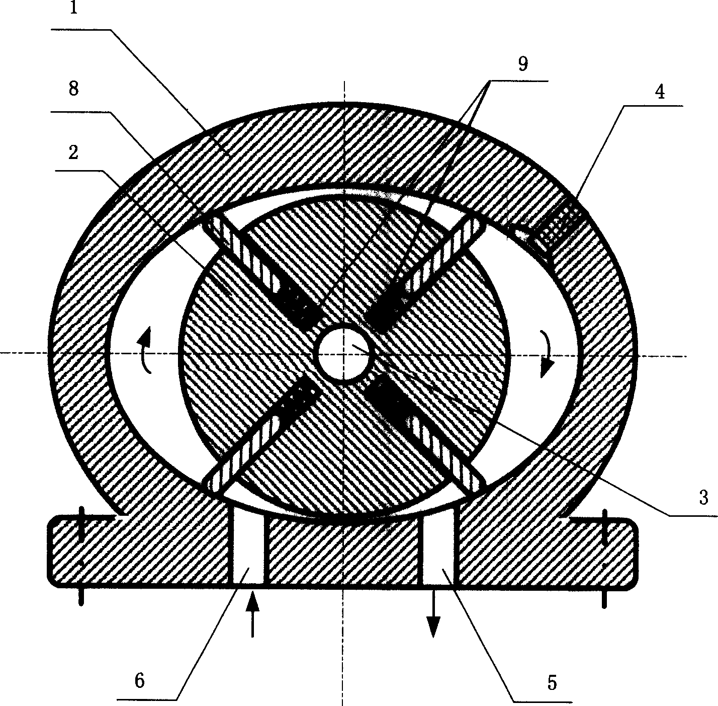
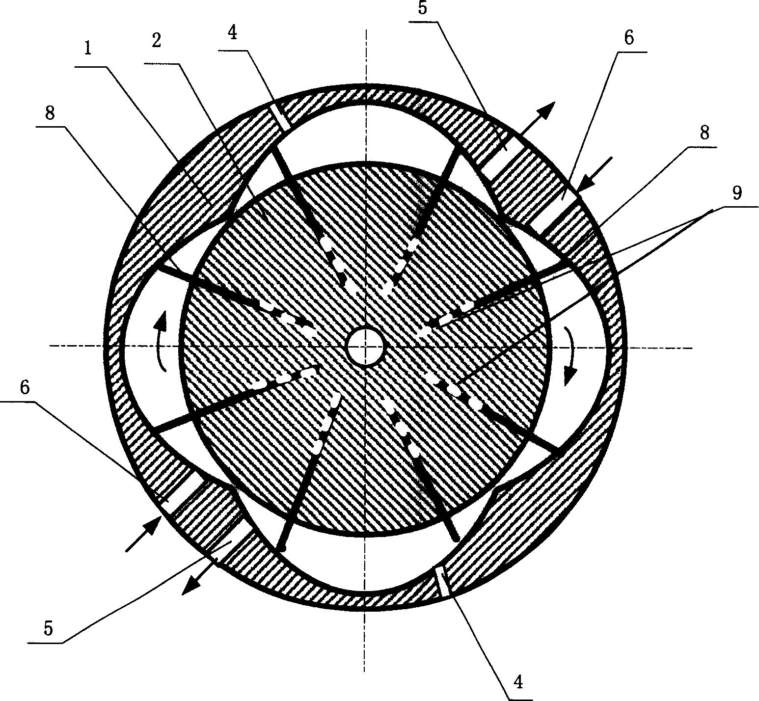
[0019] Embodiment 1: as attached Figure 4 And attached Figure 5 As shown, the rotary engine of the present invention is composed of an elliptical cylindrical stator, a rotor, a stator end cover, a shaft, a bearing, a machine base, etc., and the elliptical cylindrical stator 1 and rotor 2 are coaxial and They are not in contact with each other, and there is a gap for compressed gas to pass through; the rotor 2 divides the inner cavity of the stator 1 into two arc chambers 20 and 20', one of which communicates with the mixed gas inlet 6, and the other arc chamber The arc-shaped chamber 20' communicates with the exhaust port 5, and the ignition device 4 is installed in the arc-shaped chamber 20'.

[0020] The rotor 2 cooperates with the shaft 3 through the key 10. There are four grooves parallel to the shaft symmetrically on the rotor 2. Each groove is equipped with a spring 9 and a slide plate 8. The slide plate 8 can move radially in the groove. The spring 9 Push the slide ...

Embodiment 2

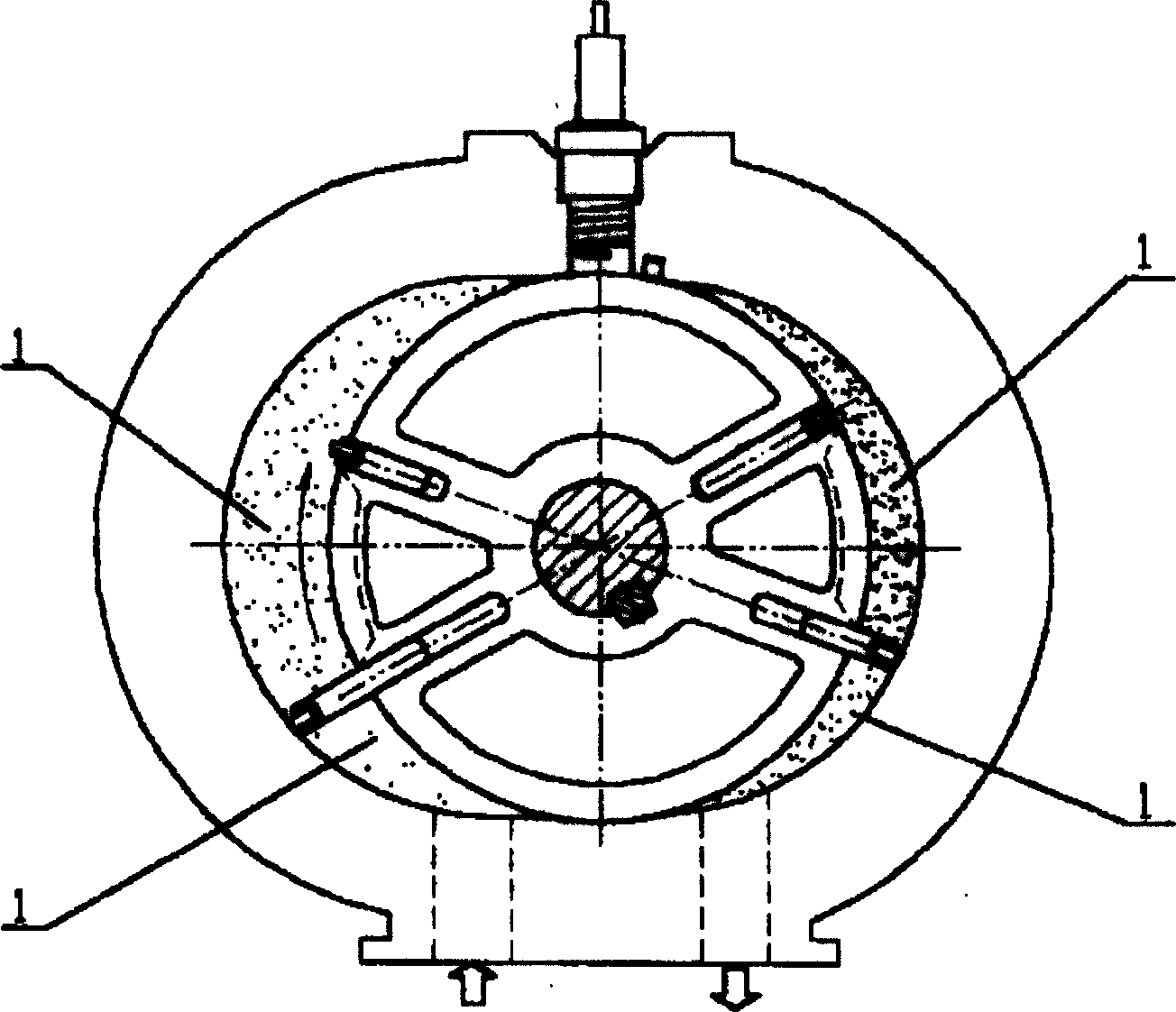
[0022] Embodiment 2: as attached Figure 4 And attached Figure 5 As shown, the structure is the same as in Example 1, the inner diameter of the minor axis of the elliptical cylindrical cavity of the stator 1 is 204mm, and the inner diameter of the major axis is 240mm; the diameter of the rotor 2 is 200mm; the diameter of the shaft 3 is 60mm; the slide plate in the groove The thickness of 8 is 8mm; the inner cavity of stator 1 and the height of rotor 2 are both 110mm; three spring seats are arranged in each channel, and small springs 9 are installed respectively; the corresponding included angle between ignition device 4 and exhaust port 5 is 117°±8'; the stator 1 is provided with several channels 7 for the flow of cooling liquid (water), and several cooling fins are also provided on the outer surface.

Embodiment 3

[0023] Embodiment 3: the same structure as Embodiment 1, as attached figure 1 And attached figure 2 As shown, a prototype of a rotary engine has been manufactured, the inner diameter of the minor axis of the elliptical cylindrical cavity of the stator 1 is 102mm, and the inner diameter of the major axis is 120mm; the diameter of the rotor 2 is 100mm; the diameter of the shaft 3 is 30mm; The thickness of the slide plate 8 is 5mm; the inner cavity of the stator 1 and the height of the rotor 2 are both 60mm; two spring seats are arranged in each channel, and a small spring 9 is installed respectively; the corresponding included angle between the ignition device 4 and the exhaust port 5 It is 116°±8'; there are several cooling fins on the outer surface.

[0024] As in the rotary engine described in Embodiment 1-3, during operation, the gas is inhaled after one of the slides passes through the gas inlet 6, and the gas between the two slides is sucked by the next adjacent slide a...


PUM


Abstract

The invention relates to a rotary engine. The internal cavity of the invention is made up of stator with elliptical cylinder or cinquefoil, cylinder type rotator, stator end cover, axis, bearing, base. The coaxial rotator and stator form 2-6 arc chambers, half of them is connected to the discharging aperture, and there has a firing device on the stator of the arc chamber; there arranges with spring and concave channel on the rotator symmetrically, the spring pushes the sliding board, another end of the sliding board is contacted to the internal surface of the stator and is sealed. The rotator rotates and absorbs the air into the aperture and is compressed, and the air enters the explosion chamber through the gap between the stator and the rotator, the firing device fires the gas, the generated explosion gas rotates to work around. The engine efficiency is high, the structure is simple, and the inlet and the discharging outlet need not single valve.

Description

Technical field: [0001] The invention belongs to the field of internal combustion engines, in particular to a rotary engine. Background technique: [0002] The internal combustion engines that are widely used at present include piston engines and turbine engines. The most common piston engines rely on explosive gas to push the pistons, and the pistons drive the crankshaft to change reciprocating motion into rotary motion; turbine engines rely on combustion expansion. The gas blowing turbine rotates to provide external work. [0003] Pistonless rotary engine, application number is 98108182.2 (publication number is CN1267354A) discloses " vane type rotary engine ", and it is that a rotor is eccentrically housed in the cylindrical cavity of stator, makes the formation between stator and rotor An arc-shaped space, the rotor is symmetrically opened with a concave groove along the radial direction, so that one end of the blade is inserted into the groove, and the other end of the...

Claims


Application Information

Patent Timeline
Patent Type & Authority Applications(China)
IPC IPC(8): F01C1/344F02B53/02
CPCY02T10/17Y02T10/12
Inventor 西姆狄科·阿纳托里·德米特利耶维奇科尔巴琴科·康斯坦丁·瓦连金诺维奇于贵
Owner 于贵
Why Eureka
Try Eureka