State machine function block with a user modifiable state transition configuration database

A state transition and function block technology, applied in the field of function blocks, can solve problems such as difficult tracking system, tedious creation of sequential function diagrams, full of errors, etc.

Active Publication Date: 2005-03-23
FISHER-ROSEMOUNT SYST INC
View PDF3 Cites 6 Cited by
  • Summary
  • Abstract
  • Description
  • Claims
  • Application Information

AI Technical Summary

Problems solved by technology

But as is known to those of ordinary skill in the art, using sequential function charts to keep track of the state of the system can be difficult
Also, similar to routines written in programming languages, creating sequential function diagrams can be tedious, time-consuming, and error-ridden

Method used


Image

  • State machine function block with a user modifiable state transition configuration database
  • State machine function block with a user modifiable state transition configuration database
  • State machine function block with a user modifiable state transition configuration database

Examples


Embodiment Construction

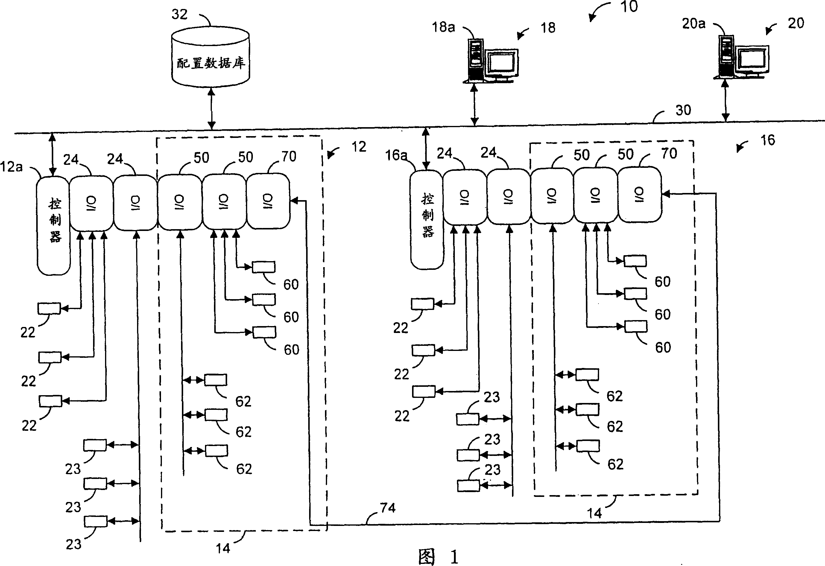
[0028] FIG. 1 is a block diagram of an example process factory 10 including one or more nodes 12 , 16 , 18 and 20 . In the example process plant 10 of FIG. 1, each of the nodes 12 and 16 includes a process controller 12a, 16a connected to one or more field devices 22 and 23 through an input / output (I / O) device 24, wherein the input Output (I / O) device 24 may be, for example, a Foundation Fieldbus interface, a HART interface, or the like. Controllers 12a and 16a are also connected to one or more hosts or operator workstations 18a and 20a in nodes 18 and 20 via a network 30, which may comprise, for example, one or more buses, wired local area networks such as Ethernet LAN ( LAN), wireless LAN, wide area network (WAN), intranet, etc. Although the control nodes 12, 16 and I / O devices 24 and field devices 22, 23 connected thereto are typically centrally located and distributed in the sometimes harsh plant environment, the operator workstation Nodes 18 and 20 are often located in ...


PUM


Abstract

A control system, a safety system, etc., within a process plant may each use one or more state machine function blocks that can be easily integrated into a function block diagram programming environment. Such a state machine function block may include one or more inputs, which may cause a state machine implemented by the state machine function block to change states. The state machine function block may determine a next state to which it is to transition based, at least in part, on data indicative of the next state to which to transition, if any. The configuration data may be retrieved from a database based on the current state of the state machine and at least one of the inputs. The state machine function block may also include one or more outputs that are generated based on the state of the state machine.

Description

technical field [0001] The present invention relates generally to function blocks for process factories, and more particularly to configuring and implementing state machines associated with process factories. Background technique [0002] Process control systems, such as those used in chemical, petroleum, or other process processes, typically include at least one host or operator workstation communicatively connected via an analog, digital, or combined analog / digital bus or line and to one or One or more process controllers for multiple field devices. Field devices, which can be, for example, valves, valve positioners, switches, and transmitters (eg, temperature, pressure, and flow rate sensors) perform functions within a process plant such as opening or closing valves and measuring process parameters. The process controller receives signals indicative of process measurements made by the field devices and / or other information related to the field devices, uses this informat...

Claims


Application Information

Patent Timeline
IPC IPC(8): G05B23/02G05B19/045
CPCG05B2219/23258G05B2219/23289G05B19/045Y02P90/02G05B19/41835
Inventor 加里·K·劳迈克尔·G·奥特肯特·A·伯尔戈弗雷·R·谢里夫
Owner FISHER-ROSEMOUNT SYST INC
Why Eureka
Try Eureka