Power unit structure for hybrid vehicle

一种混合动力车、动力单元的技术,应用在混合动力车辆、机动车、电动汽车等方向,能够解决难于保证减速比、电机尺寸增大等问题,达到提高可保养性和可触及性、缩短纵向长度、减小尺寸的效果

Inactive Publication Date: 2005-04-06
HONDA MOTOR CO LTD
View PDF1 Cites 18 Cited by
  • Summary
  • Abstract
  • Description
  • Claims
  • Application Information

AI Technical Summary

Problems solved by technology

In addition, for the above-mentioned structure in which the motor is directly connected to the drive shaft of the power transmission device, it is difficult to ensure a sufficient reduction ratio between the motor and the drive wheels.
Therefore, there is a problem that the size of the motor increases

Method used


Image

  • Power unit structure for hybrid vehicle
  • Power unit structure for hybrid vehicle
  • Power unit structure for hybrid vehicle

Examples


Embodiment Construction

[0044] An embodiment of the invention will be described with reference to the accompanying drawings, wherein like elements are designated with like numerals throughout the several views. In the following description, "front" indicates the direction in which the vehicle is advancing, and "right" and "left" indicate the right and left sides facing the advancing direction of the vehicle, respectively.

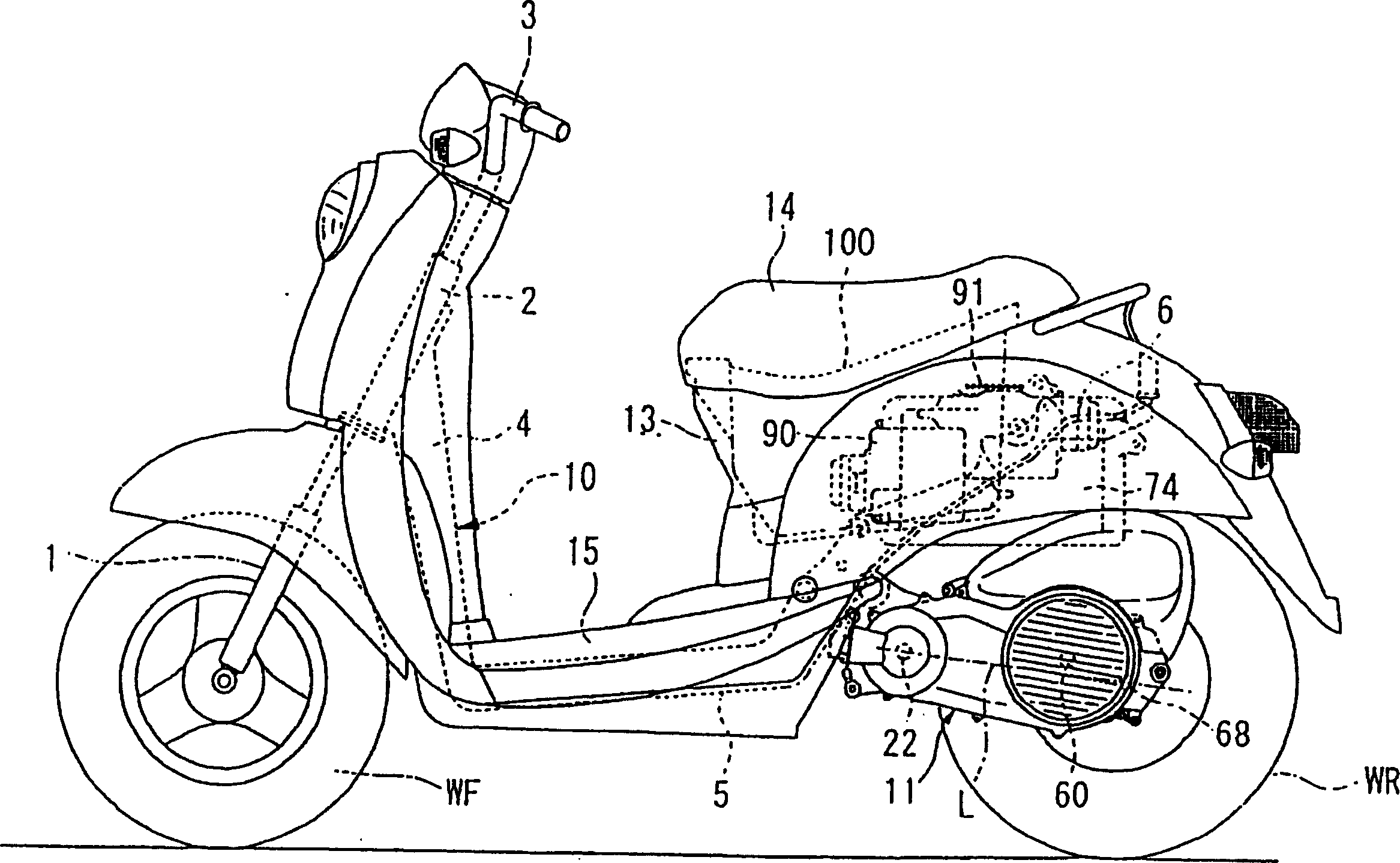
[0045] like figure 1 As shown, a hybrid vehicle according to an embodiment of the present invention is a two-wheeled integral slewing vehicle having a front fork 1 on which a front wheel WF is supported axially in front of the vehicle. The front fork 1 is pivotally installed in the head tube 2 and can be steered by operating the handle 3 . The down tube 4 extending to the rear and below is fixed on the head tube 2 . The middle bracket 5 extends horizontally from below the downcomer 4 . In addition, the rear frame 6 extends rearward and upward from the rear of the intermediate f...


PUM


Abstract

To provide desired shaft torque to a drive wheel without increasing the number of parts or increasing the size of a motor, to improve cooling capability of a generator housed inside a transmission case, and to improve energy transmission efficiency and electrical generation efficiency in an engine unit of a hybrid vehicle. A power unit structure for a hybrid vehicle is provided with an engine (20), a continuously variable transmission (23), a driven shaft (60), a drive motor (21b) and a reduction gear mechanism (69). The drive motor (21b) is attached to the reduction gear mechanism (69).

Description

[0001] Cross References to Related Applications [0002] This non-provisional application is related to Japanese Patent Applications 2003-338823, 2003-338824, 2003-338825 (each filed on September 29, 2003). The entirety of each of the above documents is incorporated into this application by reference. technical field [0003] The present invention relates to a power unit structure of a hybrid vehicle having an engine and an electric motor as power sources. Background technique [0004] In the background art, a well-known hybrid vehicle has a power transmission device for transmitting power of an engine to drive wheels mounted in a gearbox. The power transmission unit combines and transmits the power of the engine and the motor to a drive shaft (for example, Japanese Patent Publication Hei 8-175473). The hybrid vehicle disclosed in the above-mentioned document has a generator connected directly or through a reduction gear to a drive shaft in a power transmission. [0005] ...

Claims


Application Information

Patent Timeline
Patent Type & Authority Applications(China)
IPC IPC(8): B60K1/02B60K6/40B60K6/48B60K6/543
CPCY10S903/951B60Y2200/126B60K1/02B60K6/40Y10S903/912B60K6/48B60Y2200/12B62K2202/00B60K6/543Y02T10/6221Y02T10/62
Inventor 大关孝塚田善昭井元丰柴田和己
Owner HONDA MOTOR CO LTD
Why Eureka
Try Eureka