Automatic regulating flash light circuit

A flashlight circuit and automatic dimming technology, which is applied in the field of camera flashlight circuit, can solve the problems of poor automatic dimming adjustment, large VR variation range, large error value, etc., and achieve circuit stability, error value reduction, and easy adjustment Effect

Inactive Publication Date: 2005-04-13
INVENTEC MULTIMEDIA & TELECOM
View PDF0 Cites 10 Cited by
  • Summary
  • Abstract
  • Description
  • Claims
  • Application Information

AI Technical Summary

Problems solved by technology

Due to circuit feedback, traditional transistors are used for control, and the error value is large, sometimes causing malfunction
Moreover, the VR range is too large, which makes it difficult to adjust the automatic dimming at the initial setting.

Method used


Image

  • Automatic regulating flash light circuit
  • Automatic regulating flash light circuit
  • Automatic regulating flash light circuit

Examples


Embodiment Construction

[0031] Relevant detailed content of the present invention and technology, now just be described as follows with regard to coordinating accompanying drawing:

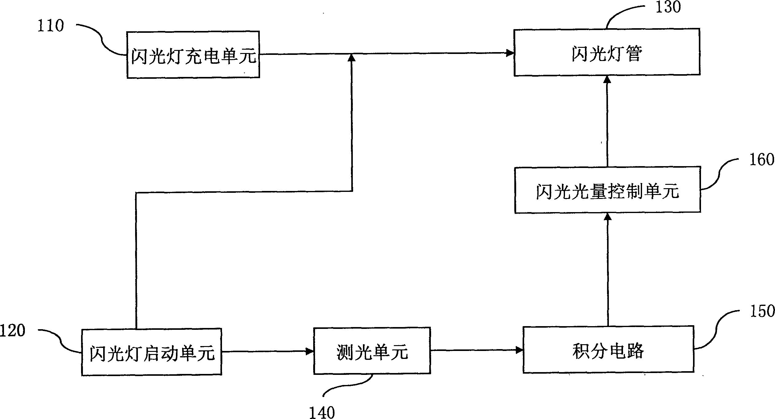
[0032] The present invention is a kind of automatic dimming flashlight circuit, at first by figure 1 The system of the present invention is described in the figure, which is a module structure diagram of the automatic dimming flashlight circuit proposed by the present invention, and is described as follows:

[0033] (1) The flashlight charging unit 110 is used to control the charging operation of the main capacitor, and determine the start and stop of the charging operation according to the voltage level of the main capacitor, so that the voltage of the main capacitor is always in an operable state. When the voltage of the main capacitor is lower than 270V, the charging operation starts, and when the voltage of the main capacitor reaches 300V, the charging operation stops.

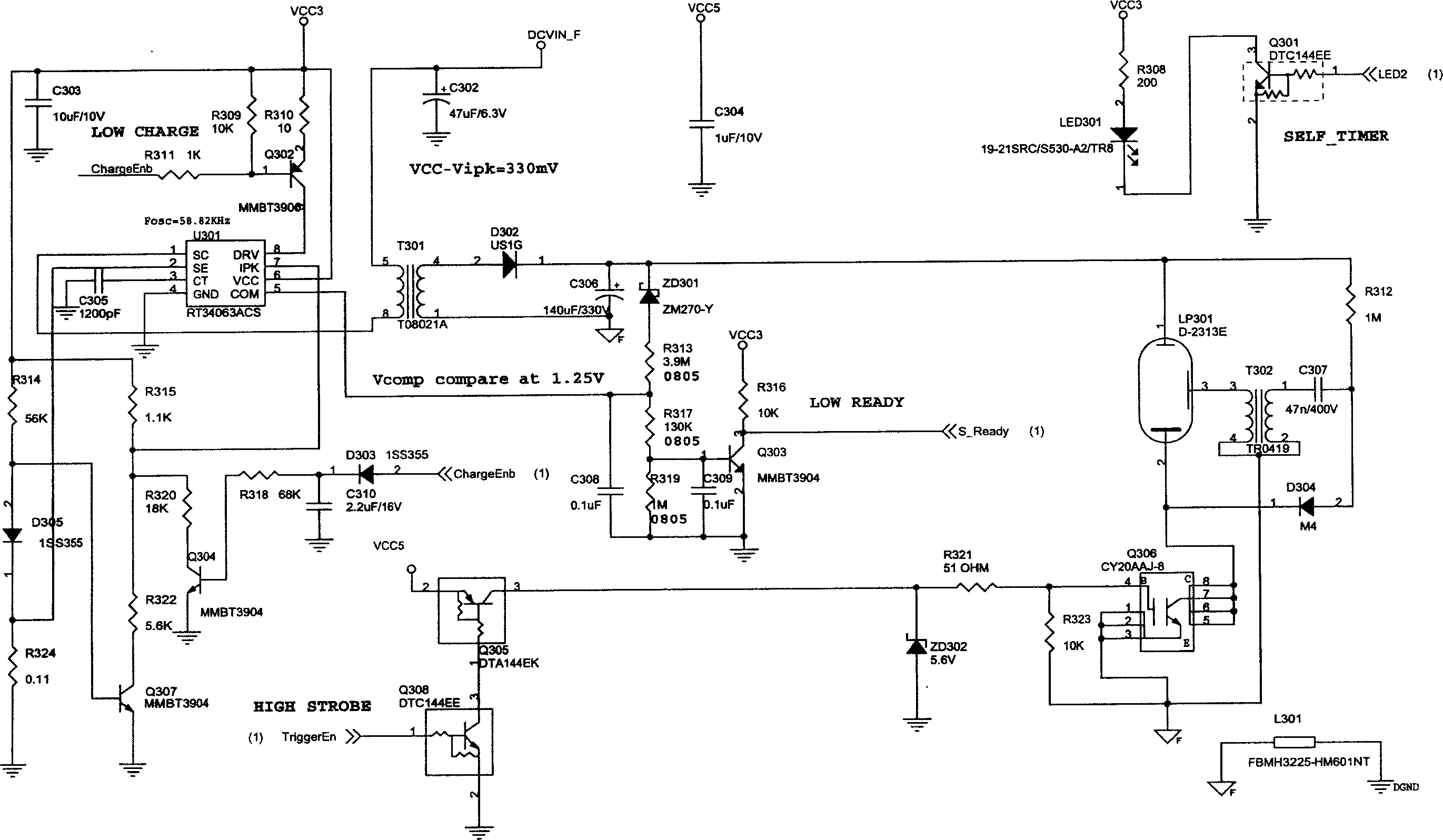
[0034] (2) The flash activation unit 120 is c...


PUM


Abstract

A light automatic adjusting flash lamp circuit includes a flash lamp charge unit, a flash start unit, a flash lamp tube, a light test unit, an integrating circuit and a flash light volume control unit, among which, the flash lamp charge unit is used to control the charging action of a master capacitor, the flash start unit starts the lamp to illuminate the shot object, the light test receives the reflecting light of the shot object and converts the energy into electric signals, the integrating circuit receives said electric signals and regulates resistance value of the integrating circuit, when its volume value reaches to the exposing standard, the control unit turns off the lamp.

Description

technical field [0001] The invention relates to a camera flash circuit, in particular to a camera flash circuit that can automatically adjust light. Background technique [0002] Flashlight is an important accessory in modern photographic equipment, and the progress and development of flashlight are synchronized with the development of science and technology. Ordinary electronic flash needs to know the distance to the subject and the sensitivity of the film used, and then calculate the required aperture to obtain the correct exposure. There is a quick reference table on the back of the flash for users to choose the aperture for shooting, but it is not so convenient to use in practice. Thus, the automatic dimming flash came into being. [0003] The automatic dimming flash is equipped with corresponding control circuits and photosensitive elements, such as figure 1 As shown, when the power is turned on, the switching characteristics of the transistor V1 are used to form an ...

Claims


Application Information

Patent Timeline
Patent Type & Authority Applications(China)
IPC IPC(8): G03B15/05H05B41/30
Inventor 曹忠铭
Owner INVENTEC MULTIMEDIA & TELECOM
Why Eureka
Try Eureka