Communication bus system operable in a sleep mode and a normal mode

A technology of sleep mode and communication bus, which is applied in the direction of transmission system, bus network, climate sustainability, etc., and can solve problems such as delay

Inactive Publication Date: 2005-04-13
NXP BV
View PDF0 Cites 4 Cited by
  • Summary
  • Abstract
  • Description
  • Claims
  • Application Information

AI Technical Summary

Problems solved by technology

This causes considerable delay

Method used


Image

  • Communication bus system operable in a sleep mode and a normal mode
  • Communication bus system operable in a sleep mode and a normal mode
  • Communication bus system operable in a sleep mode and a normal mode

Examples


Embodiment Construction

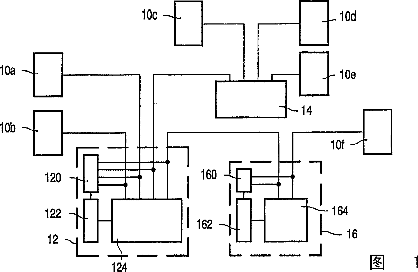
[0021] Figure 1 shows a communication bus system. The system comprises a number of node circuits 10a-f coupled by relay circuits 12,14,16. The first and second relay circuits 12 , 14 are identical and have four inputs / outputs for connection to node circuits 10 a - f and / or other relay circuits 12 , 14 , 16 . The third relay circuit 16 has two inputs and outputs. The lines connecting the node circuits 10a-f and the relay circuits 12, 14, 16 may be electrical wires or fiber optic connections. Although a single line is shown connecting the node circuits 10a-f and the relay circuits 12, 14, 16, it will be understood that in practice more than one line, eg a pair of electrical conductors, may be used to conduct different voltages or currents.

[0022] More specifically, the first and third relay circuits 12,16 are shown as including detector circuits 120,160, mode control circuits 122,162 and transceiver circuits 124,164. The transceiver circuits 124 of the relay circuits 12,16 ...


PUM


Abstract

The communication bus system comprises a plurality of node circuits ( 10 a-d) and a relay circuit ( 12, 14, 16 ) coupling the node circuits ( 10 a-d). The relay circuit ( 12, 14, 16 ) has a transceiver circuit ( 124, 164 ) for relaying messages ( 21 ) between the node circuits ( 10 a-d) in a normal mode. The transceiver circuit ( 124, 164 ) is powered down in a sleep mode. A detector circuit ( 120, 160 ) detects an incoming message ( 41 ) when the relay circuit ( 12, 14, 16 ) is in a sleep mode. A mode control circuit ( 122, 162 ) powers up the transceiver ( 124, 164 ) in response to detection of an incoming message ( 21 ). Steps are taken that ensure, in the normal mode, that messages ( 21 ) will not be relayed in unreadable form. The mode control circuit ( 122, 162 ) is arranged to cause the transceiver ( 124, 164 ) to relay a remainder ( 25 ) of the incoming message ( 21 ) after power up. In an embodiment the power needed to transmit the remainder ( 25 ) of the message ( 21 ) is drained from a capacitor ( 306 ) in the power supply ( 30 ) before the power supply ( 30 ) controls the power supply voltage in the normal mode. In another embodiment the detector circuit ( 120, 160 ) temporarily controls the direction of operation of the transceivers ( 124, 164 ) at the start of the normal mode instead of further detectors ( 58 a-d) that normally control the direction of operation in the normal mode.

Description

technical field [0001] The present invention relates to communication bus systems. [0002] A communication bus system is a known solution for providing shared communication lines for communication between different pairs of nodal circuits. For example, one approach to sharing a communication line is to assign different time slots to different node circuits, so that each node circuit can send messages in its own time slot without conflicting with other node circuits. Background technique [0003] PCT Patent Application No. 99 / 46888 describes a bus system capable of switching to a sleep mode when the system consumes less power than the normal operating mode. Often there may be no node circuit sending a message for a considerable period of time. This can be exploited to reduce the power consumption of the system. For this purpose the system can be switched to sleep mode during such periods. In sleep mode, the main part of each node circuit is powered down except for a smal...

Claims


Application Information

Patent Timeline
IPC IPC(8): G06F1/26G06F1/32G06F3/00H04B1/38H04L12/28H04L29/00
CPCG06F1/3203G06F1/3253Y02D10/00H04L12/40G06F1/32
Inventor P·W·H·霍特斯H·博伊泽H·G·J·沃斯S·G·E·布特塞拉亚尔
Owner NXP BV
Why Eureka
Try Eureka