Ultrasonic image color display device and method

A color display, ultrasonic technology, applied in ultrasonic/sonic/infrasonic diagnosis, measurement device, sonic diagnosis and other directions, to achieve the effect of improving the speed of reading pictures

Inactive Publication Date: 2005-04-20
CLEAR SOUNDS TECH SHANGHAI CO LTD
View PDF0 Cites 7 Cited by
  • Summary
  • Abstract
  • Description
  • Claims
  • Application Information

AI Technical Summary

Problems solved by technology
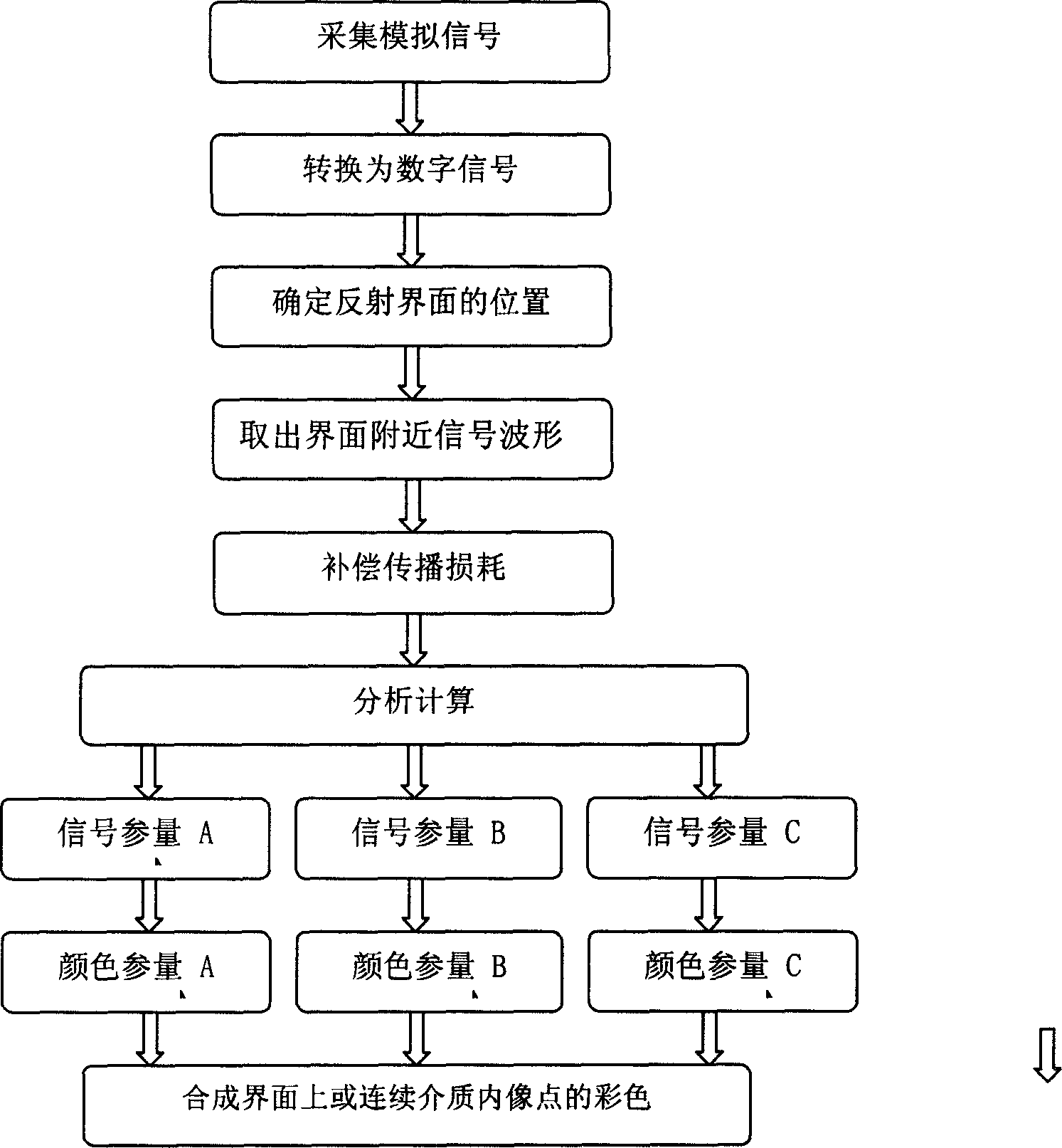
Unfortunately, existing medical imaging techniques, including ultrasound imaging, utilize only a tiny fraction of the bandwidth of the human eye

Method used


Image

  • Ultrasonic image color display device and method

Examples


Embodiment 1

[0038] The signal parameter combination of the ultrasonic color image in this embodiment is:

[0039] A: The fundamental component of the main signal;

[0040] B: The second harmonic component of the main signal;

[0041] C: The difference between the fundamental component and the second harmonic component;

[0042] The feature of this embodiment: the fundamental wave and the second harmonic effect are simultaneously displayed in the same image. Assume that the color parameters A is red, B is green, and C is blue. At the image point where the second harmonic is the strongest, the green is the strongest, the blue is the weakest, and the overall color of the image point is yellowish. At the image point where the second harmonic is the weakest, the green is the weakest, the blue is the strongest, and the overall color of the image point is purple. In order to highlight the nonlinear characteristics of the target tissue, the signal parameter B of each image point can be multip...

Embodiment 2

[0044] With embodiment 1, the difference is that the signal parameters of the ultrasonic color image are combined as follows:

[0045] A: The maximum positive amplitude of the main signal;

[0046] B: The maximum negative amplitude of the main signal;

[0047] C: vacancy;

[0048] Features of this embodiment: This is a two-parameter embodiment. Compared with the traditional black-and-white or pseudo-color images based on the maximum signal amplitude, this embodiment can effectively display the different influences of different image points on the reflected signal waveform. When there is a change in the acoustic properties of the acoustic interface but no change in the geometric properties, the position of the reflected signal remains unchanged, and sometimes the maximum amplitude does not change, but the waveform always changes. The increase and decrease between positive and negative amplitudes is one of the most obvious ways of waveform change, which is effectively shown b...

Embodiment 3

[0050] With embodiment 1, the difference is that the signal parameters of the ultrasonic color image are combined as follows:

[0051] A: The maximum peak value of the main signal;

[0052] B: The peak value of the left lobe of the maximum peak value of the main signal;

[0053] C: The peak value of the right lobe of the maximum peak value of the main signal;

[0054] Features of this embodiment: Compared with the previous example, it can reflect the relative changes of the three lobes at the same time, which is more conducive to highlighting the ultra-thin layer structure near the interface and other parts on the interface that have a significant impact on the signal waveform.


PUM


Abstract

The invention discloses an ultrasonic image color display device and method suitable for industrial detection and medical diagnosis. This method extracts multiple physical quantities from the ultrasonic signal corresponding to each image point of the detected target to define the color of the image point. The color image obtained by this method can simultaneously display the spatial distribution of multiple physical quantities on the detected target, which contains far more abundant information about the detected target than any traditional ultrasonic image, making full use of the bandwidth of the human eye for color images, The far richer and easier-to-recognize information is transmitted to the brain of the map reader in the first time, which greatly improves the speed of map reading, and the recognition rate and accuracy of abnormal phenomena. The color ultrasonic image proposed by the present invention, while maintaining the traditional ability to detect the position of the acoustic interface in the measured object, can also provide the effective expression of the continuous medium between the interfaces that the traditional ultrasonic instrument lacks.

Description

technical field [0001] The invention relates to an ultrasonic image color display device and method, in particular to an ultrasonic image color display device and method suitable for industrial non-destructive testing and medical diagnosis. Background technique [0002] The color ultrasound medical imaging currently used in the market, usually referred to as "color ultrasound", is essentially a black and white ultrasound reflection image plus a color Doppler blood flow map. It can be said that ultrasound image technology is still in the era of black and white, that is, the era of B-ultrasound. Here the English capital letter B stands for the English word Brightness, which means brightness. The full name of B-ultrasound should be Brightness Ultrasound Imager. Industrial ultrasonic testing is even further behind in its use of images. [0003] There is another class of medical ultrasound imagers with color displays on the market. This type of ultrasound imager displays blac...

Claims


Application Information

Patent Timeline
IPC IPC(8): A61B8/00G01N29/00G03B42/06
Inventor 文荆江
Owner CLEAR SOUNDS TECH SHANGHAI CO LTD
Why Eureka
Try Eureka