Temperature sensor circuit
一种温度传感器、电路的技术,应用在电路、温度计、仪器等方向,能够解决很难、很难输出电压VOUT设置成目标电压等问题,达到输出电压高精确的效果
- Summary
- Abstract
- Description
- Claims
- Application Information
AI Technical Summary
Problems solved by technology
Method used
Image
Examples
no. 1 example
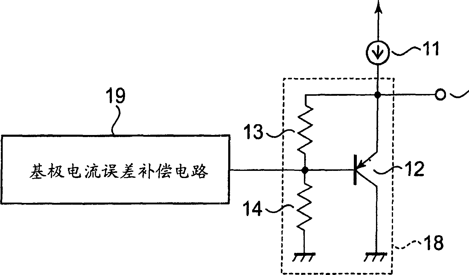
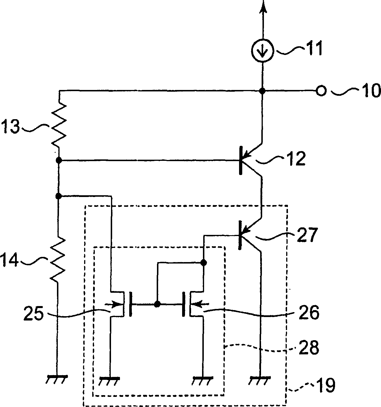
[0021] The temperature sensor circuit according to the first embodiment of the present invention is figure 1 shown in . exist figure 1 The temperature sensor circuit of the first embodiment shown in FIG. 7 is such that a base current error compensation circuit 19 is provided in the temperature sensor circuit shown in FIG. 7 . For example, something like figure 2 As shown in , the base current error compensation circuit 19 includes a bipolar transistor 27 whose base is connected to the drain of the second N-channel MOS transistor 26, and composed of the first N-channel MOS transistor 25 and The second N-channel MOS transistor 26 constitutes a current mirror circuit 28 . Note that it is assumed that the characteristics of the bipolar transistors 12 and 27 are equal to each other, and their emitter sizes are also equal to each other, and that the characteristics of the first and second N-channel MOS transistors 25 and 26 are also equal to each other, and their transistor size...
no. 2 example
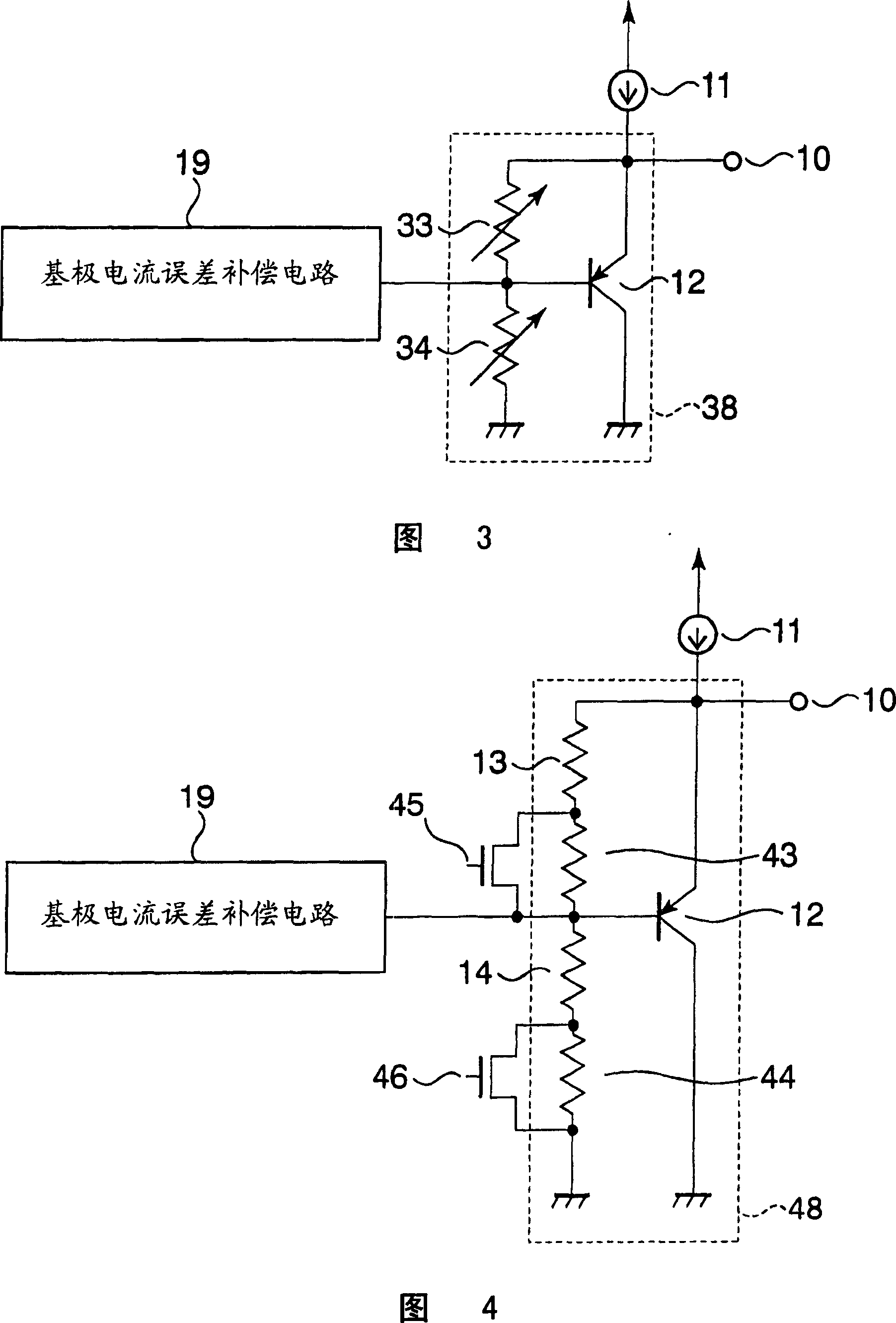
[0023] A temperature sensor circuit according to a second embodiment of the invention is shown in FIG. 3 . In the temperature sensor of the first embodiment, the first and second resistors 13 and 14 are provided as fixed resistors. However, in the case of the first embodiment, if the drift of the output voltage VOUT due to dispersion in the characteristics of the bipolar transistors 12 and 27 and in the characteristics of the first and second resistors 13 and 14 is considered, then Then the fine adjustment of the output voltage VOUT is essentially the design of the temperature sensor circuit. In this case, at least one of the first and second resistors 13 and 14 of the first embodiment is replaced by a variable resistor, thus allowing the output voltage VOUT to be finely adjusted. As a result, the output voltage VOUT is set with higher accuracy than with fixed resistors.
no. 3 example
[0025] A temperature sensor circuit according to a third embodiment of the present invention is shown in FIG. 4 . In the temperature sensor circuit shown in FIG. 4, the variable resistors of the temperature sensor circuit according to the second embodiment are constructed of MOS switches. With this circuit configuration, the resistance value of the first or second resistor can be finely adjusted by the ON / OFF operation of the MOS switch at a stage of post circuit production, thus enabling precise setting of the output voltage VOUT .
PUM
 Abstract
Description
Claims
Application Information
 - R&D
- Intellectual Property
- Life Sciences
- Materials
- Tech Scout
- Unparalleled Data Quality
- Higher Quality Content
- 60% Fewer Hallucinations
Browse by: Latest US Patents, China's latest patents, Technical Efficacy Thesaurus, Application Domain, Technology Topic, Popular Technical Reports.
© 2025 PatSnap. All rights reserved.Legal|Privacy policy|Modern Slavery Act Transparency Statement|Sitemap|About US| Contact US: help@patsnap.com


