AC generator for a vehicle

a technology for ac generators and vehicles, applied in the direction of windings, magnetic circuit rotating parts, magnetic circuit shapes/forms/construction, etc., can solve the problems of increasing manufacturing costs and reducing so as to reduce the variation of thermal stress in the parts of the end cover, prolong the durability of the end cover or increase the effect of the durability

Inactive Publication Date: 2010-08-24
DENSO CORP
View PDF15 Cites 4 Cited by
  • Summary
  • Abstract
  • Description
  • Claims
  • Application Information

AI Technical Summary

Benefits of technology

[0008]It is an object of the present invention to provide an AC generator for a vehicle equipped with an end cover of a high durability without increasing the size of the AC generator and without increasing the amount of resin. To achieve the above purposes, the present invention provides an AC generator for a vehicle has a frame and an end cover. The frame accommodates a rotor and a stator. The end cover is made of mold resin. The end cover is fixed to the frame and accommodates electrical components including a rectifier device. The rectifier device is capable of rectifying an output voltage of a stator coil of the stator which is fixed to an outer end surface of the frame. The rectifier device has a flat plate part extending approximately in a radius direction, a rib part projecting from the plate part toward the end cover, and a cooling fin part facing the end cover. In the AC generator, the end cover has a first part which is close to the rib part of the rectifier device and a second part which is close to the flat plate part and away from the rib part. The first part is stronger in anti-thermal stress than the second part. The rib part in the AC generator of such a type increases a discharging area of the cooling fin and also increases the rigidity of the cooling fin. In particular, in the AC generator for a vehicle according to the present invention, the first part (corresponding to “the rib-part adjacent part” in the embodiments, which is mostly close to the rib part of the rectifier device) is thinner in thickness than the second part of the end cover.

Problems solved by technology

Because such a thermal stress occurs repeatedly every becoming a high temperature of the cooling fins, the durability of the end cover decreases.
This increases a manufacturing cost.

Method used


Image

  • AC generator for a vehicle
  • AC generator for a vehicle
  • AC generator for a vehicle

Examples


first embodiment

[0024]A description will now be given of an AC generator for a vehicle (or a vehicular alternator) according to the first embodiment of the present invention with reference to FIG. 1 to FIG. 3.

(Entire Configuration)

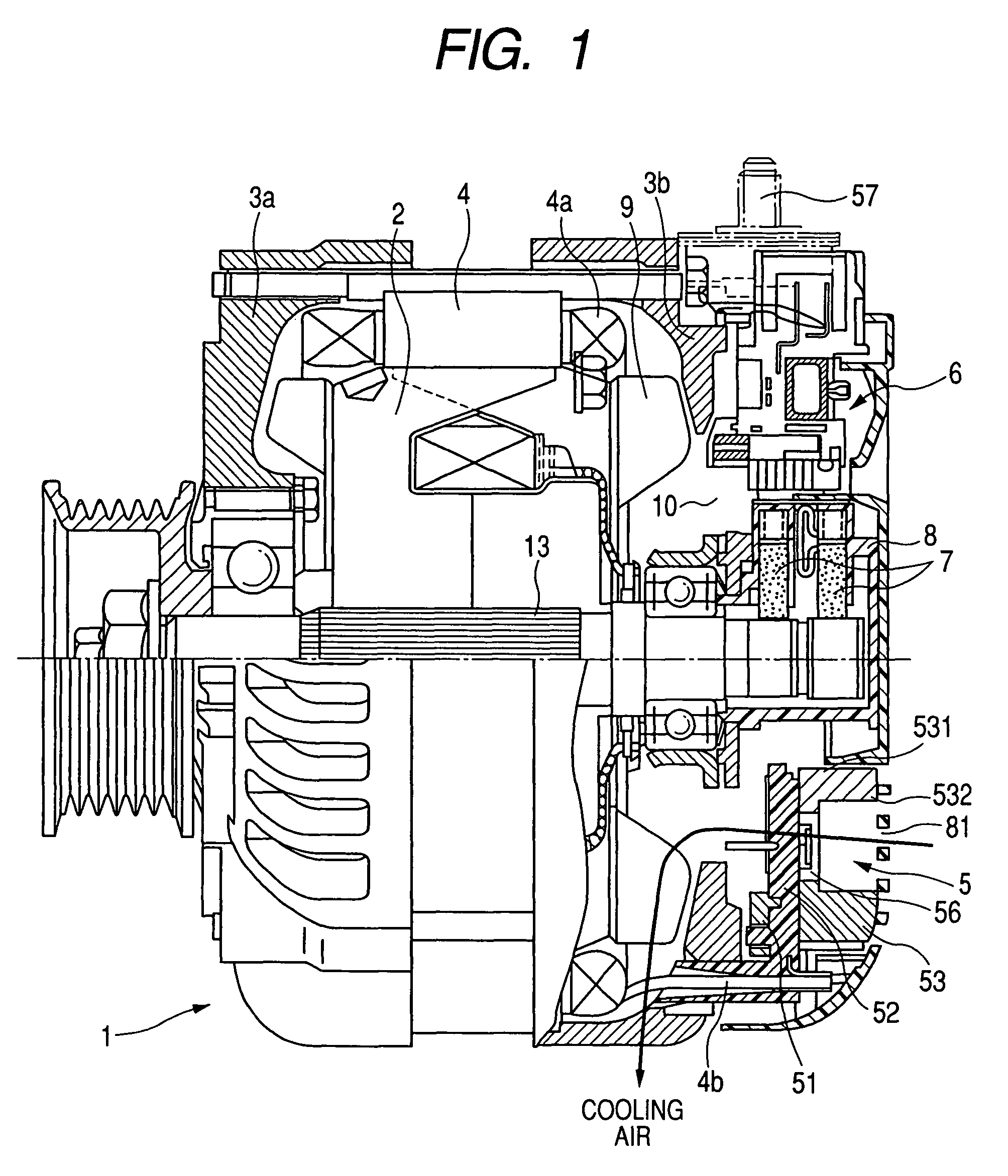
[0025]FIG. 1 is a cross sectional view of the AC generator for a vehicle along its axial direction according to the first embodiment of the present invention.

[0026]The AC generator 1 for a vehicle has a rotor 2, a front frame 3a, a rear frame 3b, a stator 4, a rectifier device 5, a regulator 6, and a brush assembly 7. The rotor 2 rotates by a rotary power transmitted from a vehicular engine (not shown) through a pulley and a belt (not shown). The front frame 3a and the rear frame 3b rotatably support the rotor 2 through bearings. The stator 4 accommodates the rotor 2 therein and is fixed to the front frame 3a and the rear frame 3b. The stator 4 has stator coils 4a in which an AC voltage is induced by a rotating magnetic field generated by rotating the rotor 2. The rectifi...

second embodiment

[0039]A description will now be given of an AC generator for a vehicle according to a second embodiment of the present invention with reference to FIG. 4. FIG. 4 is a partial sectional view of the positive fins 53 (or a cooling fin) and the end cover 8-1 along the axial direction of the AC generator for a vehicle according to the second embodiment.

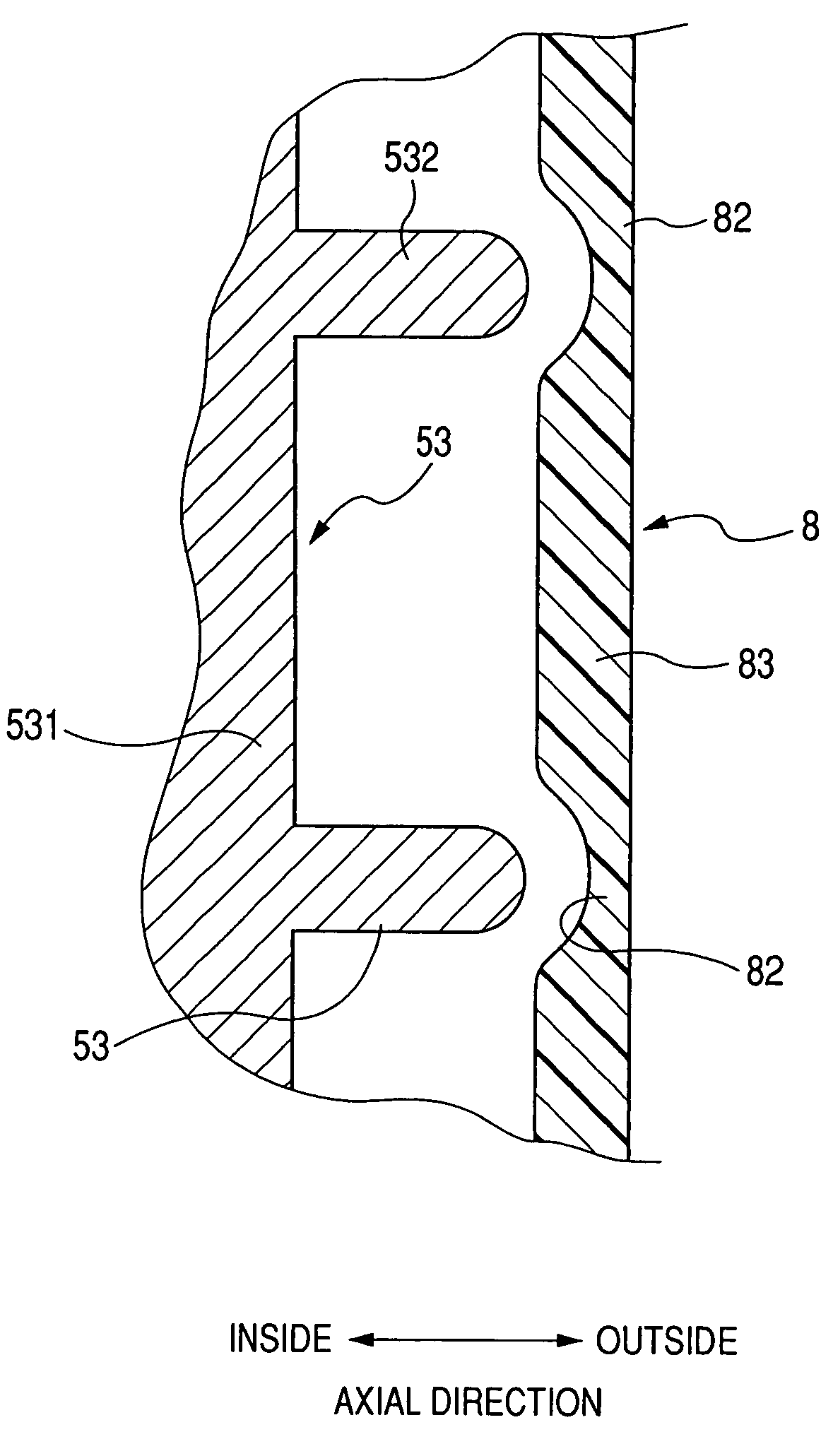
[0040]The end cover 8-1 of the AC generator according to the second embodiment shown in FIG. 4 is different in configuration from the end cover 8 of the AC generator according to the first embodiment shown in FIG. 3.

[0041]As shown in FIG. 4, the rib-part adjacent part 82-1 in the end cover 8-1, which is close to the rib part 532 of the positive fin 53, is curved toward the outside of the end cover 8-1 when compared with the plate-part adjacent part 83-1 which is away from the rib part 532.

[0042]This configuration shown in FIG. 4 can also decrease the variation of thermal stress which is different in the rib-part adjacent part 82-1 and the ...

third embodiment

[0043]A description will now be given of an AC generator for a vehicle according to a third embodiment of the present invention with reference to FIG. 5. FIG. 5 is a partial sectional view of the positive fin 53 and the end cover 8-2 along the axial direction of an AC generator for a vehicle according to the third embodiment.

[0044]In the configuration of the end cover 8-2 according to the third embodiment, each rib-part adjacent part becomes each opening window of the cooling air flow sucking window 81 (see FIG. 1 and FIG. 5). The plate-part adjacent part 83-2 corresponds to the plate-part adjacent part 83 shown in FIG. 3. This configuration shown in FIG. 5 can also decrease the variation of thermal stress which is different in the rib-part adjacent part and the plate-part adjacent part 83-2 in the end cover 8-2, and thereby can increase the anti-thermal fatigue.

[0045]Because each rib part 532 is formed in a radial pattern, the cooling air flow sucking window 81 has each opening win...


PUM


Abstract

In an AC generator for a vehicle, an end cover has two types of parts, one-type part is away from a rib part in a positive cooling fin, and the other-type part is close to the rib part. The rib part projects toward the end cover side. The one-type part is thinner than the other-type part in the end cover in order to reduce the variation of thermal expansion in each part of the end cover. This configuration increases anti-thermal fatigue of the end cover.

Description

CROSS-REFERENCE TO RELATED APPLICATION[0001]This application is related to and claims priority from Japanese Patent Application No. 2006-242916 filed on Sep. 7, 2006, the contents of which are hereby incorporated by reference.BACKGROUND OF THE INVENTION[0002]1. Field of the Invention[0003]The present invention relates to an AC generator (or a vehicular alternator) for a vehicle, in particular, relates to a vehicular alternator equipped with a resin end cover (hereinafter, referred to as “an end cover” in short) covering electrical components attached to an outer end surface of a frame.[0004]2. Description of the Related Art[0005]For example, Japanese patent laid open publication No. JP H11-164538 has disclosed an AC generator having a configuration in which an end cover covers a rectifier device to an outer end surface of a frame. The end cover has a cooling window through which cooling air flows from the outside of the AC generator into the inside thereof in order to cool the recti...

Claims


Application Information

Patent Timeline
Patent Type & Authority Patents(United States)
IPC IPC(8): H02K1/32
CPCH02K11/046H02K9/06H02K11/05
Inventor KOUMURA, MASATOSHITAN, YOSHIKIKOIKE, AKIHITO
Owner DENSO CORP
Why Eureka
Try Eureka