Floor laying material, piece mat, and arranging structure thereof

A technology for arranging structures and floor mats, which is used in floor covering, thin material processing, other household appliances, etc., can solve the problems of high noise level, reduce the sound absorption performance of the cabin, and achieve the effect of reducing the noise level.

Inactive Publication Date: 2005-05-04
HAYASHI GIJUTSU KENKYUSHO KK
View PDF1 Cites 4 Cited by
  • Summary
  • Abstract
  • Description
  • Claims
  • Application Information

AI Technical Summary

Problems solved by technology

Therefore, floor mats laid in the car cabin will reduce the sound absorption performance in the car cabin, resulting in higher noise levels

Method used


Image

  • Floor laying material, piece mat, and arranging structure thereof
  • Floor laying material, piece mat, and arranging structure thereof
  • Floor laying material, piece mat, and arranging structure thereof

Examples


example 1

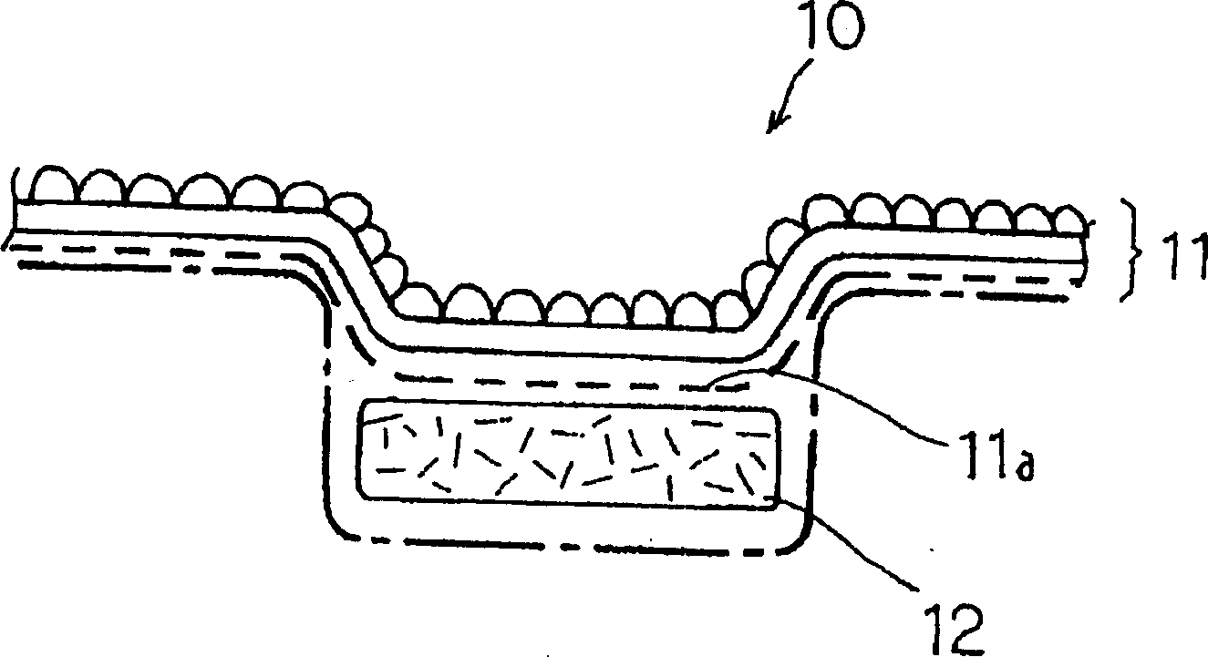
[0087] On the following permeable floor covering 10, the below-mentioned floor mat 20 is provided.

[0088] The floor covering material 10 used in the present example was made by the following process: at a flow resistance value of 400 Nsm -3 On the carpet-like layer 11 made of needle-punched carpet, the laminate thickness is 30mm and the density is 0.1g / cm 3 The cushioning material layer 12 made of polyester fiber felt is made.

[0089] In addition, the flow resistance value of the floor mat 20 used in this example is 100Nsm -3 , which is made by using 100g / m2 per unit area 2 The short fiber of dispersed polyethylene resin is formed as the adhesive layer of the bonding tape 23, and the per unit area is 100g / m 2 A layer 24 of cushioning material made of polyester resin non-woven fibers is laid on a support of 600g / m2 per unit area 2 On the base fabric layer 22 of the woven fleece layer 21, 120g / m per unit area 2 The back of the base fabric is a latex product (latex work) ...

example 2

[0091] On the same floor covering 10 as in Example 1, the following floor mat 20 was provided.

[0092] The flow resistance value of the floor mat 20 used in this example is 500Nsm -3 , which is made by using 150g / m per unit area 2 The short fiber of dispersing polyethylene resin is formed as the adhesive layer of bonding tape 23, will be per unit area 250g / m 2 A cushion material layer 24 made of polyester resin non-woven fibers is attached to a support of 600g / m2 per unit area 2 On the base fabric layer 22 of the woven fleece layer 21, 120g / m per unit area 2 A latex product with SBR (styrene-butadiene-rubber) resin coated on the back of the base fabric layer.

example 3

[0094] On the same floor covering 10 as in Example 1, the following floor mat 20 was provided.

[0095] The flow resistance value of the floor mat 20 used in this example is 1000Nsm -3 , which is made in the following way: by 350g / m 2 The short fiber of dispersing polyethylene resin is formed as the adhesive layer of bonding tape 23, will be per unit area 550g / m 2 A cushion material layer 24 made of polyester resin non-woven fibers is attached to a support of 600g / m2 per unit area 2 On the base fabric layer 22 of the woven fleece layer 21, 120g / m per unit area 2 A latex product with SBR (styrene-butadiene-rubber) resin coated on the back of the base fabric layer.


PUM

PropertyMeasurementUnit
thicknessaaaaaaaaaa
thicknessaaaaaaaaaa
thicknessaaaaaaaaaa

Abstract

A floor laying material whose sound absorbing property and sound insulating property are optimized; a piece mat; and an arranging structure thereof. A floor laying material (10) comprises a carpet layer (11) having joining strips (11a) of thermoplastic resin discontinuously arranged on the back surface thereof, and a cushion material layer (12) laminated to the back surface of the carpet layer (11) through the joining strips (11a). The carpet layer (11) has its front-to-back flow resistance value adjusted to be between 100 Nsm-3 and 1000 Nsm-3. Further, the cushion material layer (12) is made of a raw material having an air wrapping property and has its front-to-back flow resistance value adjusted to be between 40 Nsm-3 and 800 Nsm-3.

Description

technical field [0001] The present invention relates to a floor covering laid on a floor panel of a vehicle compartment to reduce noise in the vehicle compartment, a piece mat provided on the floor covering, and an arrangement structure thereof. Background technique [0002] Conventionally, in order to reduce the noise in the space of the car (such as the cabin, trunk, engine room, etc.), it is known that an important factor lies in controlling the paving materials laid in the space of the car, especially the interior covering of the car body as an interior material Or the flow resistance value (permeability) of the carpet (carpet) and the partition noise reduction device between the engine and the cab and other decorative materials. [0003] In patents JP-51-112889-A, JP-56-142054-A, JP-59-186750-A, etc., there are disclosed prior art related to controlling such flow resistance value. These prior arts all attempt to improve the sound absorption of the noise damper by setti...

Claims


Application Information

Patent Timeline
Patent Type & Authority Applications(China)
IPC IPC(8): B32B5/26B32B7/02B32B7/14B60N3/04B60R13/08D06N7/00G10K11/16G10K11/162
CPCB60R13/083Y10T428/23986D06N7/0086D06N2201/02D06N7/0076D06N2209/12D06N2209/025D06N2211/267D06N2211/266D06N2205/04B32B7/02Y10T428/23979D06N2203/068D06N2211/263D06N2205/10B32B5/26B32B7/14D06N2211/066D06N7/0081D06N7/0036B60N3/048G10K11/16G10K11/162B60R13/08B32B2262/0276B32B2471/02B32B5/026B32B5/022B32B7/12B32B2605/00
Inventor 今村优仁中村利幸
Owner HAYASHI GIJUTSU KENKYUSHO KK
Why Eureka
Try Eureka