Trolley for moving building

A pulley and fixed seat technology, applied in building maintenance, construction, building construction, etc., can solve the problems of high work intensity, increased traction resistance, high cost, etc., and achieve the effect of high reuse rate, lower traction force, and steel saving.

Inactive Publication Date: 2005-05-11
山东建筑工程学院
View PDF0 Cites 4 Cited by
  • Summary
  • Abstract
  • Description
  • Claims
  • Application Information

AI Technical Summary

Problems solved by technology

The disadvantage of this kind of walking device is: the rollers are easy to deflect when they enter the upper and lower tracks, and the distance between the rollers is difficult to be uniform. Uneven, prone to deflection. After the rollers are deflected, the traction resistance will increase, and the building will easily deflect horizontally, increasing the difficulty of translation control. At the same time, it will also generate additional lateral force on the upper and lower rails. As a result, the actual force of the

Method used


Image

  • Trolley for moving building
  • Trolley for moving building
  • Trolley for moving building

Examples


Example Embodiment

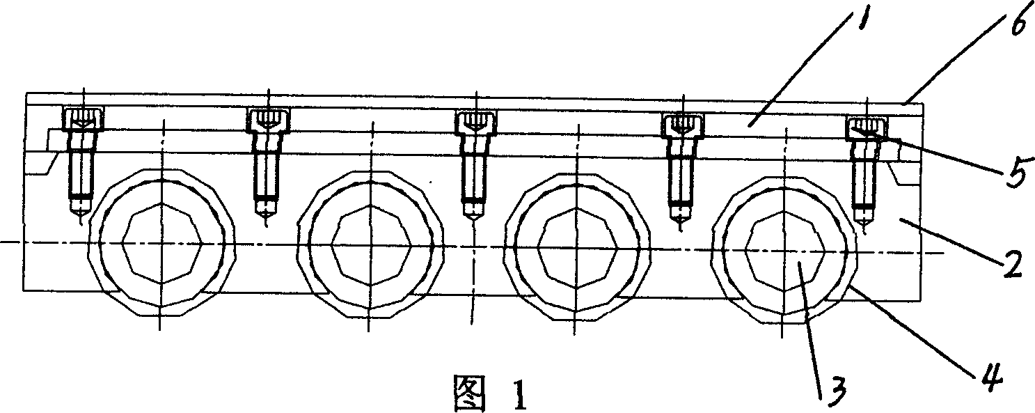
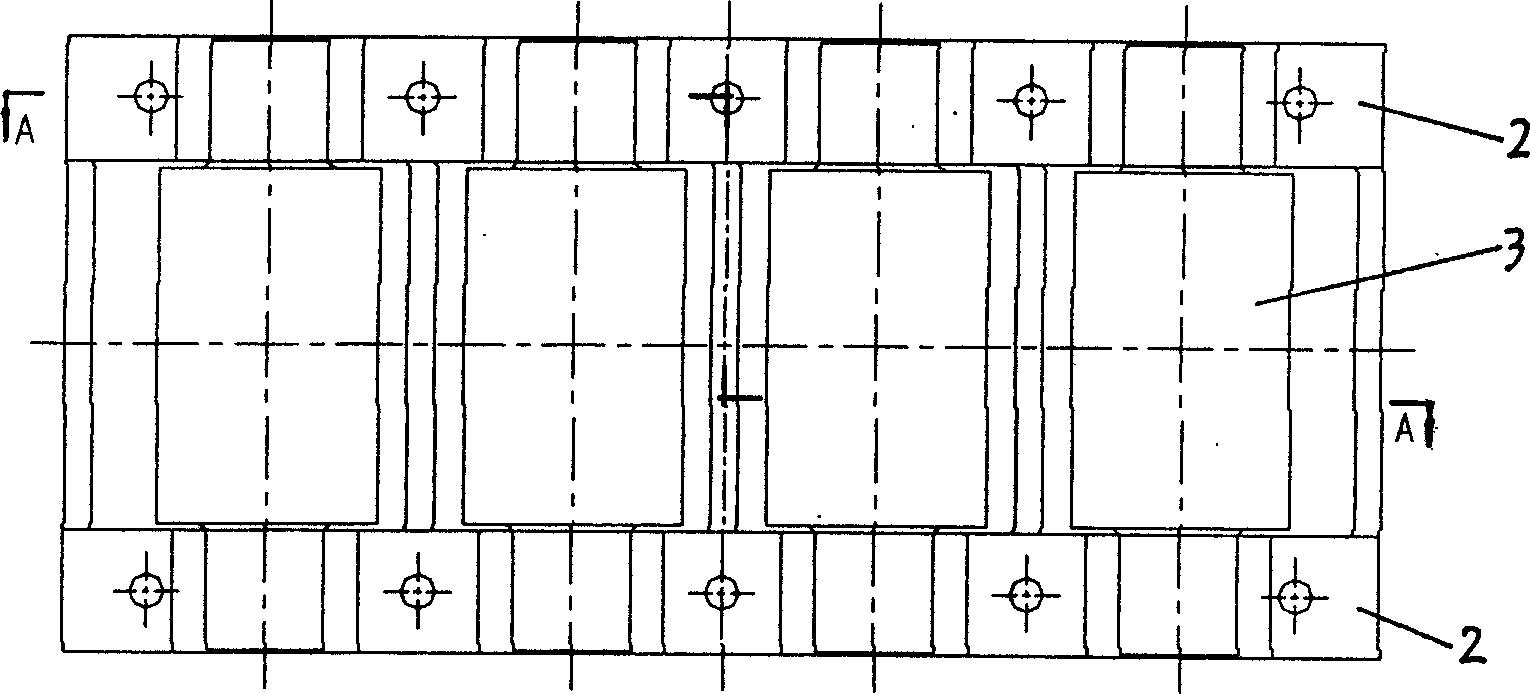
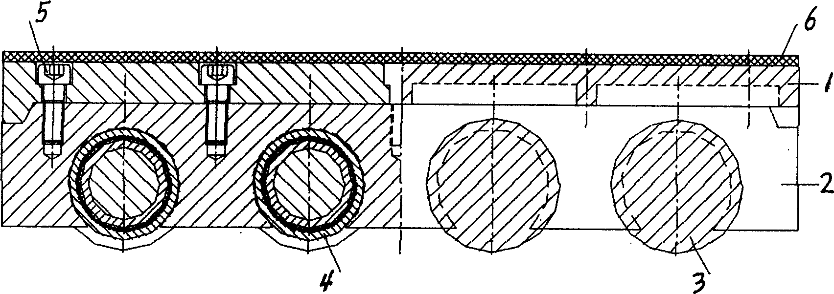
[0015] In Figure 1, figure 2 , image 3 In the structural diagram of the present invention given, the fixing seat is composed of a top plate 1 and two side plates 2, and the side plates are fastened under the top plate with bolts 5. Each roller 3 is installed between the two side plates 2 through a needle bearing 4, and a rubber plate 6 is provided on the top plate 1.

[0016] in Figure 4 , Figure 5 In the schematic diagram shown, the roller 3 of the moving block 11 is in contact with the lower rail 9, the upper rail beam 8 is supported on the rubber plate 6 of the moving block 11, and the weight of the translation building 7 is transmitted to the block 11 through the upper rail beam 8 On the top plate 1 and finally transferred to the lower rail 9 by the trolley roller 3. As shown in the figure, when the building is moving in translation, the stress point of the upper rail beam 8 remains unchanged when the sliding block of the present invention is used. But in the case of ordin...


PUM


Abstract

A slide vehicle for moving building is composed of a fixing platform, several rollers installed under said fixing platform, and a rubber plate laid on the fixing platform. It can control the direction and the stress of upper track beams well.

Description

(1) Technical field [0001] The invention relates to a walking device for building translation. (2) Background technology [0002] The overall movement of buildings is a special industry in the construction industry. Although it has only a history of more than ten years in our country, it has played a very important role in urban reconstruction and construction. The running device is an important equipment in building translation. At present, the walking device used in domestic building translation projects is mainly rollers. Whether it is a solid steel roller or a hollow steel roller (concrete or cement mortar) roller, each roller The shafts are independent of each other. During the translation process, the rollers enter the upper and lower tracks one by one and exit sequentially. The exiting rollers need to be manually transferred to the front end of the building in the forward direction and need to be rearranged. Therefore, a certain number of Turnover rollers. The disad...

Claims


Application Information

Patent Timeline
IPC IPC(8): E04G23/06
Inventor 贾留东张鑫徐向东
Owner 山东建筑工程学院
Why Eureka
Try Eureka