Drill and production method thereof

一种钻头、旋转方向的技术,应用在制造工具、修钻、麻花钻等方向,能够解决刀尖部1′刚性降低等问题

Inactive Publication Date: 2005-05-25
MITSUBISHI MATERIALS CORP
View PDF1 Cites 30 Cited by
  • Summary
  • Abstract
  • Description
  • Claims
  • Application Information

AI Technical Summary

Problems solved by technology

[0015] However, since the angle of departure is given over the entire length of the nose portion 1′, when it is desired to provide a sufficient undercut on the outer peripheral surface of the nose portion 1′ to add a large angle of departure, it is necessary to place the nose The outer diameter of the part 1' is reduced beyond the required range at its rear end, so there is a problem that the rigidity of the tip part 1' decreases.

Method used


Image

  • Drill and production method thereof
  • Drill and production method thereof
  • Drill and production method thereof

Examples


Embodiment

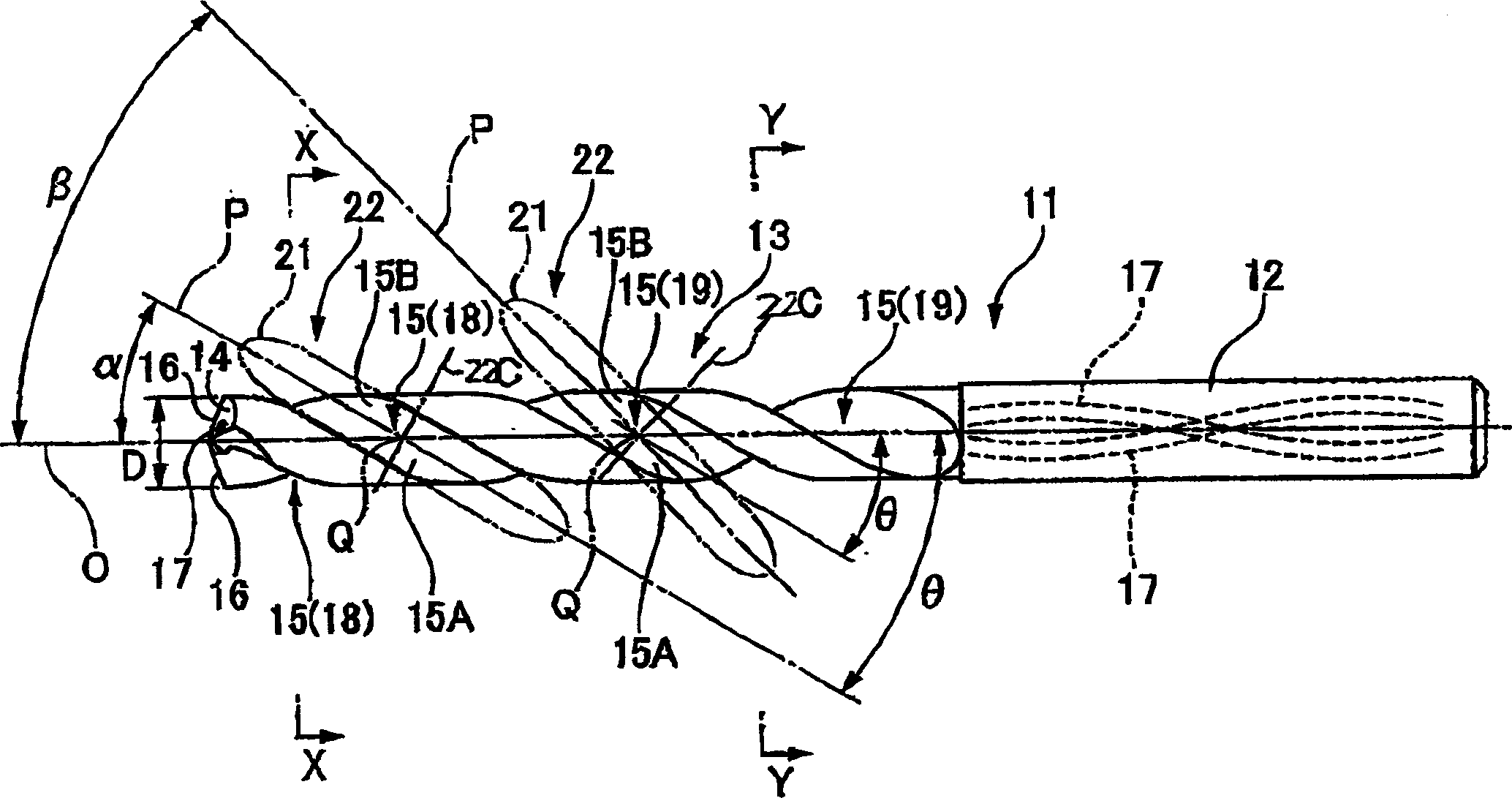
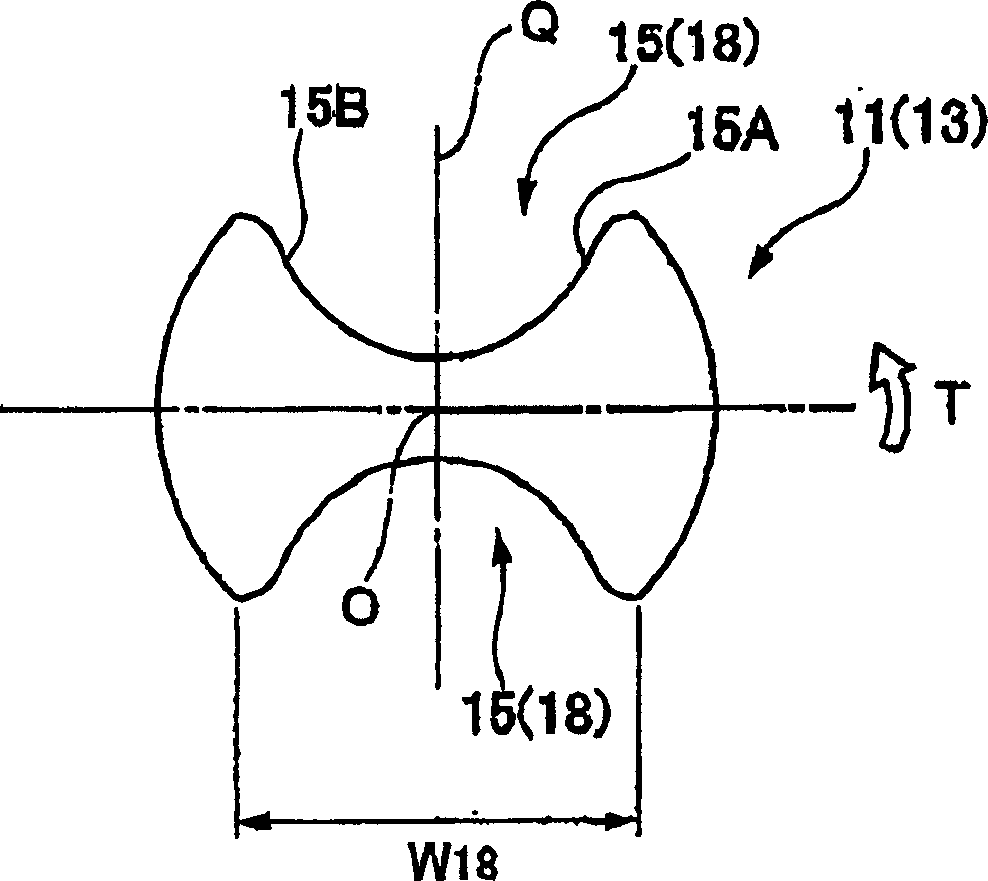
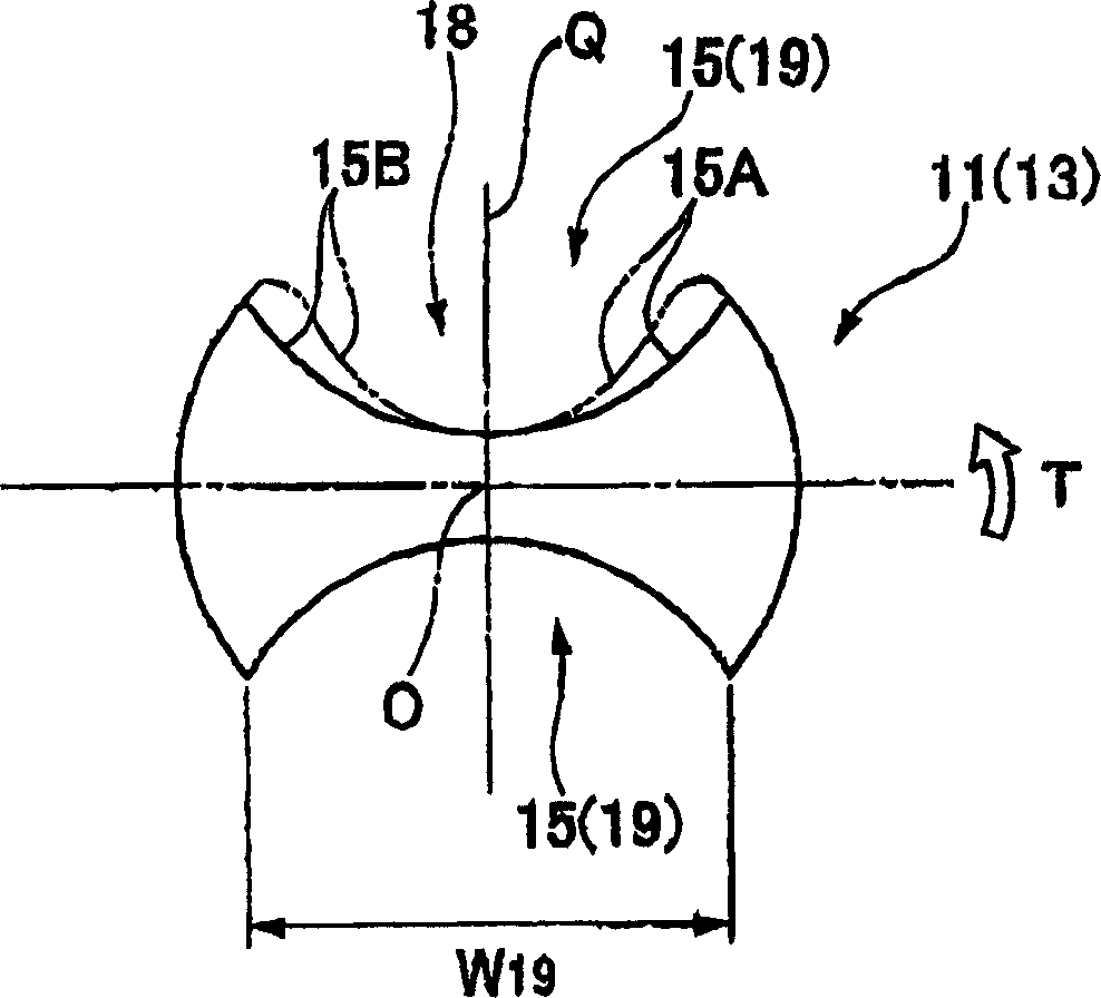
[0151] for illustration Figure 11 to Figure 17 The effect of the drill bit shown will be based on the Figure 11 to Figure 17 Cutting tests were performed on the double-edged drill of the embodiment shown as an example, and the double-edged drill of the prior art as a prior art example. The results are shown in Figure 18 .

[0152] It can be seen that, in the embodiment as an example of the present invention, the roughness of the inner wall surface of the inlet portion and the outlet portion of the machining hole is well kept small, whereas in the prior art example, The roughness of the inner wall surface of the inlet part and the outlet part of the processing hole deteriorates.

[0153] Figure 19 to Figure 21 Another embodiment of the drill bit of the present invention is shown.

[0154] In the drill of this embodiment, the drill main body 201 is formed of a hard material such as cemented carbide and has a substantially cylindrical shape centered on the axis O, and it...


PUM


Abstract

A drill comprising a first margin section, which is adjacent to the rear side in the direction of drill rotation of the chip discharge groove, and a second margin section, which is adjacent to the front side in the direction of drill rotation of the chip discharge groove, formed in a land section of the drilling end section; wherein a thinning section (140) is formed on the tip side of the inner wall surface of the chip discharge groove that is continuous with the inner peripheral edge of the cutting edge and extends to the land section.

Description

technical field [0001] The present invention relates to a drill in which helical chip discharge grooves are formed on the outer periphery of a tip end portion of a drill body and a method for manufacturing the same. Furthermore, the present invention relates to a drilling drill for forming a machining hole with a high level of hole position accuracy in a workpiece, for example, a drill for forming a deep hole in a metal material. Background technique [0002] As a drill (solid drill) in which a helical chip discharge groove is formed on the outer periphery of the tip portion of the drill body, for example, Figure 22 to Figure 24 As shown, on the outer periphery of the tip portion of the substantially cylindrical drill body 1 that rotates around the axis O, the rotation direction of the drill around the axis O is formed symmetrically with respect to the axis O from the top end clearance of the drill body to the rear end side. A pair of chip discharge flutes 2 twisted on the ...

Claims


Application Information

Patent Timeline
Patent Type & Authority Applications(China)
IPC IPC(8): B23B51/00B23B51/02B23B51/06B24B19/04
CPCB23B51/02B23B51/06B23B2224/24B23B2224/28B23B2224/32B23B2224/36B23B2228/10B23B2251/04B23B2251/046B23B2251/14B23B2251/18B23B2251/406B23B2251/443B24B3/24B24B19/04Y10T408/78Y10T408/909Y10T408/9097B23B51/063
Inventor 马渕雅行柳田一也铃木克征泷口正治
Owner MITSUBISHI MATERIALS CORP
Why Eureka
Try Eureka