Driving system for rotary tools in a tool holder turret

A drive system, a technology for rotating tools, applied in drive devices, mechanical drive clutches, manufacturing tools, etc., can solve problems such as jeopardizing the accuracy of the turret, complex crown assembly systems, and difficult modularization of the rotary tool rest table.

Inactive Publication Date: 2005-06-01
迪普马自动化公开有限公司
View PDF1 Cites 6 Cited by
  • Summary
  • Abstract
  • Description
  • Claims
  • Application Information

AI Technical Summary

Problems solved by technology

This latest technical solution, on the one hand it has the advantage of taking up less axial space, on the other hand it has the serious disadvantage of requiring costly machining for the preparation of the crown, which has a large diameter , capable of withstanding the stresses created by the forces acting on the tool when it is driven, another disadvantage is the need for a complex system of tooth crown assembly,

Method used


Image

  • Driving system for rotary tools in a tool holder turret
  • Driving system for rotary tools in a tool holder turret
  • Driving system for rotary tools in a tool holder turret

Examples


Embodiment Construction

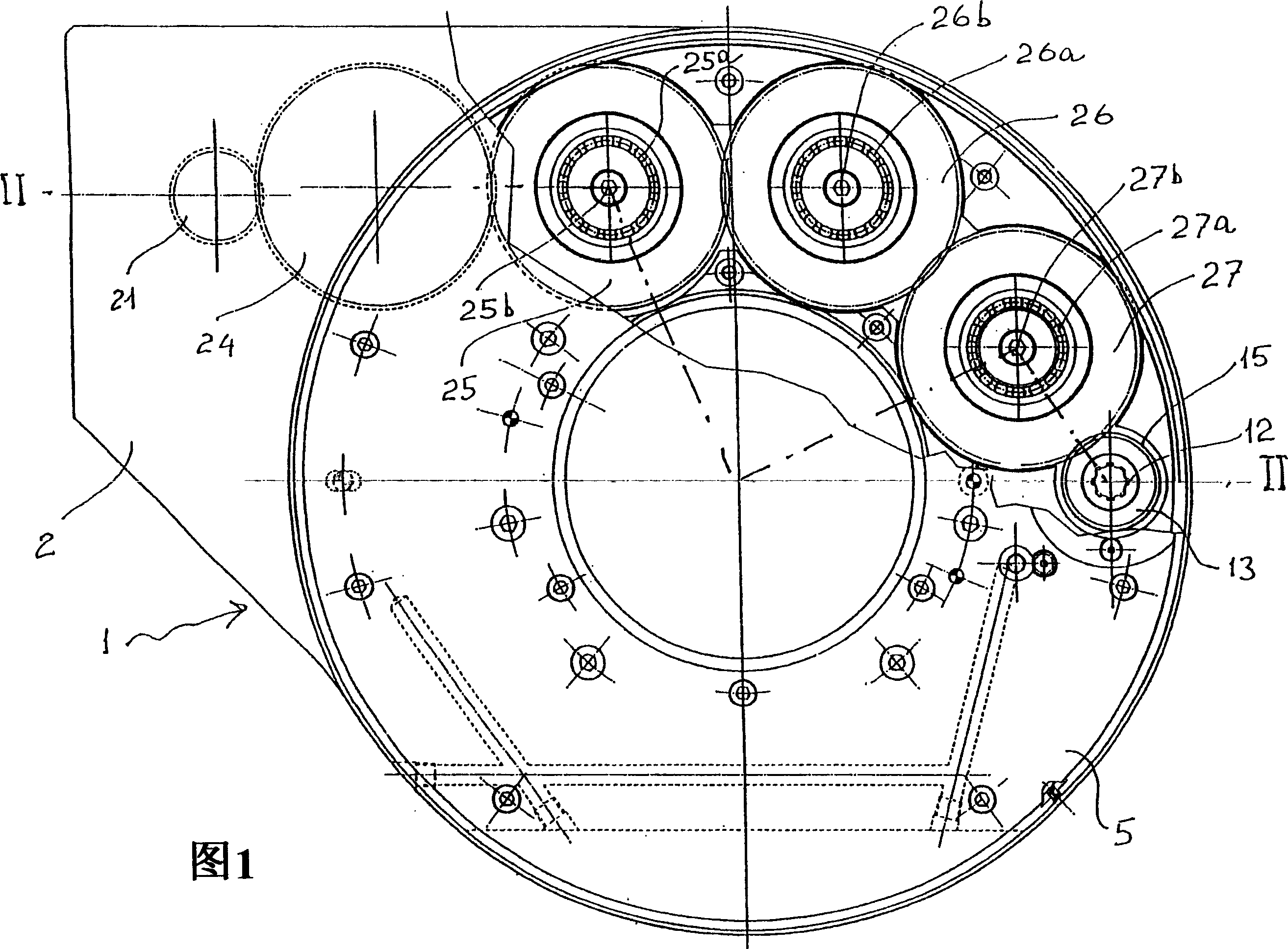
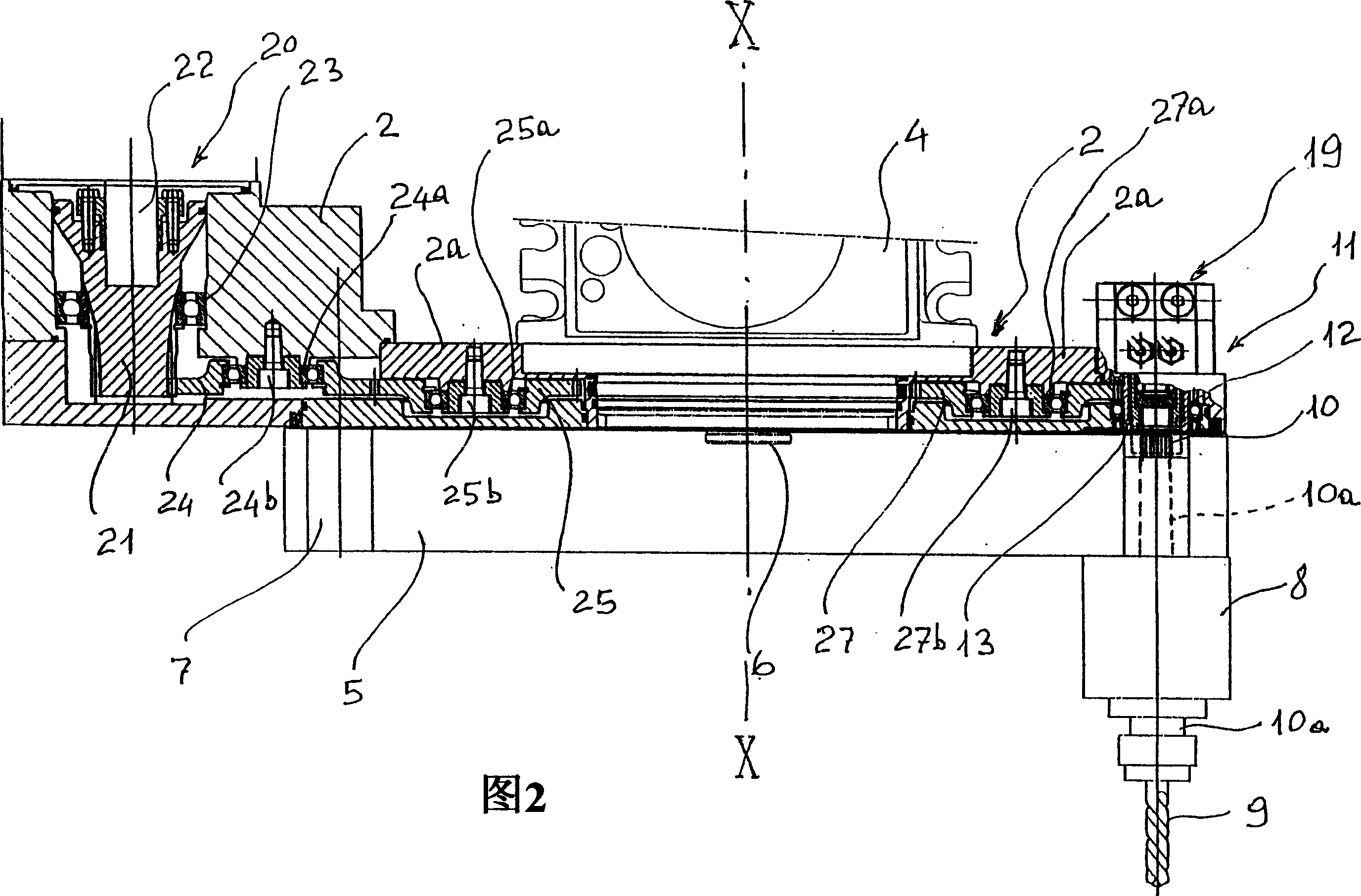
[0019] With reference to the aforementioned drawings, the tool holder worktable, especially the worktable for mounting the rotary drill bit and the boring tool, is generally represented by 1.

[0020] The stationary part of the workbench includes a main body 2 with a cavity 3 extending around the longitudinal axis X-X; the main body 2 is designed to be connected to the fixed part 4 of a conventional turret partially shown in the figure.

[0021] The rotating part of the worktable is denoted by 5, which is connected with the rotating part of the turret denoted by shaft 6. The axis of the shaft 6 coincides with the axis XX to change the angle of the working position of the tool around the axis XX The displacement occurs in a conventional manner.

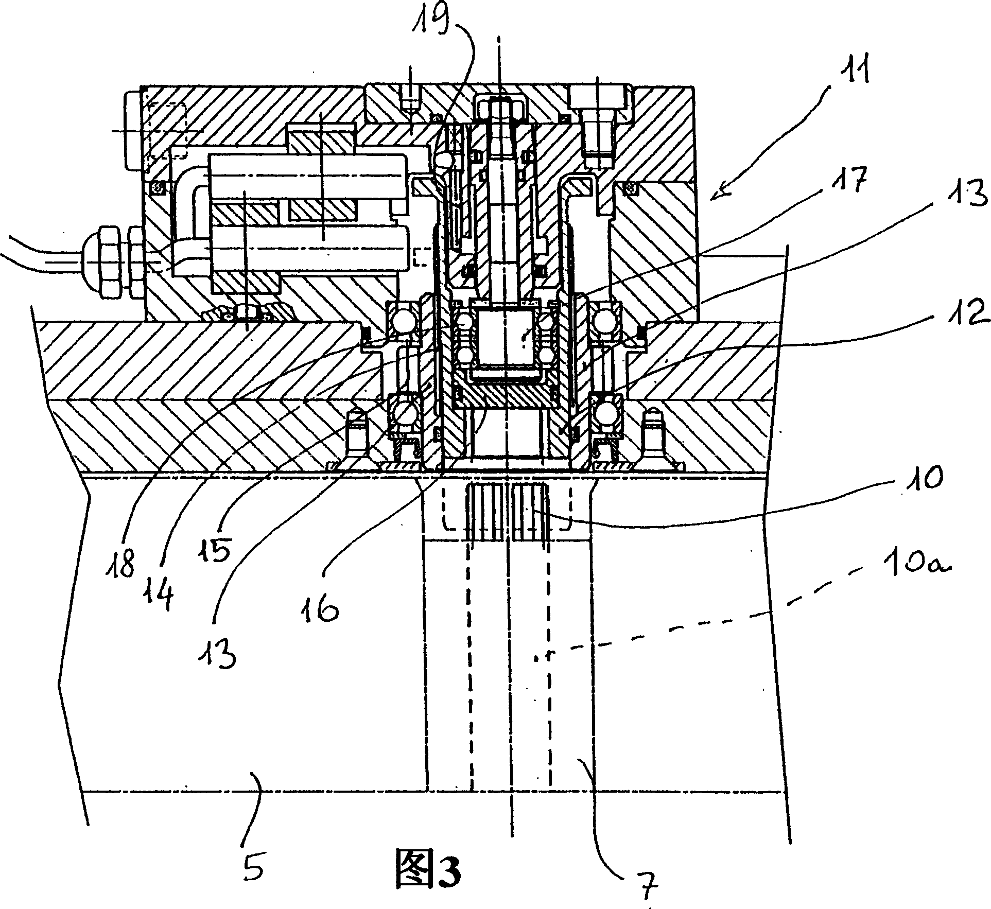
[0022] On the rotating part 5, a bracket 7 for the mandrel 8 is formed in a circumferential area, such as a rotating tool indicated by 9 in the drawing, fixed therein.

[0023] In these conventional mandrels 8, the shafts of their respecti...


PUM


Abstract

Driving system for rotary tools, in tool holder turrets for lathes, machining centres and the like, of the type comprising a stationary base body (2) with a cavity (3) which extends around a longitudinal axis (X-X), a tool holder table (5) which is rotatable with respect to the stationary base body (2) about a rotatiional axis coaxial and coinciding with the longitudinal axis (X-X) of said cavity (3), a plurality of tool housings (7) formed on said table (5) and distibuted along a circumferential zone of the table, each of said housings (7) being equipped with a respective spindle (8) for holding a rotary tool (9) comprising a motion receiving shaft (10a) arranged parallel to said rotational axis (X-X) of the table, a drive shaft (13) for the rotatio of the tools rotatably mounted on said stationary base body (2) with its rotational axis also parallel to said rotational axis (X-X) of the table, motor members (6) for angulary displacing the table (5) about said rotational axis (X-X) to take the motion receiving shaft (10a) of one of any of said tool holder spindles (8) in axial alignment with said drive shaft (13), means (12) capable of being displaced upon command, housed on said stationary body (2), for coupling and decoupling said drive shaft (13) with the motion receiving shaft (10a) of the tool holder spindle which, following the rotation of the table, is aligned with it, driving means (20, 21), mounted on said stationary base body (2) to make said drive shaft (13) for rotating the tools rotate.

Description

Technical field [0001] The invention relates to a driving system for a rotary tool in a tool post turret of a lathe, a machining center, and the like. Background technique [0002] As we all know, lathes and especially machining centers must be able to perform a large number of different types of machining, not only with fixed cutting tools but also with rotary tools. Rotary tools are suitable for drilling, boring and the like on the workpiece. operating. [0003] Therefore, the table for mounting the rotary tool of the turret, which can replace the table with the holder for the fixed tool, must be equipped with a holder with a spindle capable of receiving and mounting the rotary tool. [0004] Moreover, it must have drive components for rotating the spindle when the tool needs to be activated at certain times for the intended operation. [0005] Examples of worktables with rotating tool holders for turrets having the above general characteristics are shown in GB-A-2.126.143 and ...

Claims


Application Information

Patent Timeline
IPC IPC(8): B23Q5/04B23Q5/38B23Q16/02B23Q39/02F16D11/14
CPCB23Q5/04B23Q2220/002
Inventor 佛朗哥·德·贝尔纳迪
Owner 迪普马自动化公开有限公司
Why Eureka
Try Eureka