Component part in cavity die body for filling concrete

A cavity mold and component technology, which is applied to building components, building structures, floor slabs, etc., can solve the problems of inconvenient production, inconvenient assembly line production, and low production efficiency

Inactive Publication Date: 2005-06-15
湖南邱则有专利战略策划有限公司
View PDF1 Cites 3 Cited by
  • Summary
  • Abstract
  • Description
  • Claims
  • Application Information

AI Technical Summary

Problems solved by technology

However, when the formwork member in this floor slab is produced, it is inconvenient to make, the production efficiency is low, it is not convenient for assembly line production, and the corresponding cost is high. Therefore, it is urgently needed to develop a new type of concrete filling cavity formwork member

Method used


Image

  • Component part in cavity die body for filling concrete
  • Component part in cavity die body for filling concrete
  • Component part in cavity die body for filling concrete

Examples


Embodiment Construction

[0064] The present invention will be further described below in conjunction with the accompanying drawings and embodiments.

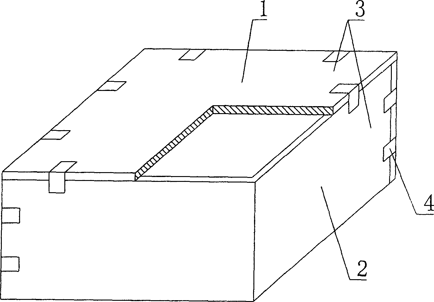
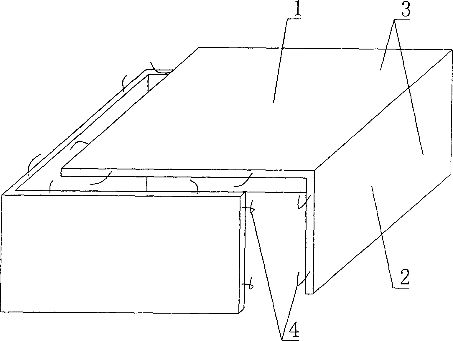
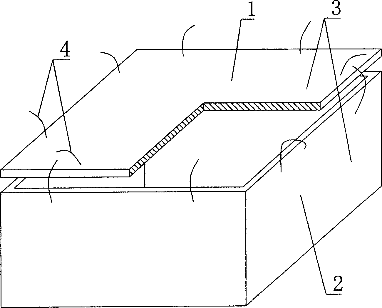
[0065] As shown in the accompanying drawings, the present invention includes an upper plate 1 and surrounding side walls 2, and the upper plate 1 and the surrounding side walls 2 form an open cavity formwork, which is characterized in that at least two of the cavity formworks are prefabricated The plates 3 are assembled, and there are at least two conjoined prefabricated plates in the prefabricated plates 3. The prefabricated plates 3 are assembled into an open cavity or a closed cavity, and the prefabricated plates 3 are connected by a connecting piece 4 as a whole. . figure 1 It is a structural schematic diagram of Embodiment 1 of the present invention. In the accompanying drawings, 1 is the upper plate, 2 is the surrounding side wall, 3 is the prefabricated plate, and 4 is the connector. In the following drawings, those with the same number have the...


PUM


Abstract

The invention relates to a concrete infilling hollow cavity form member, including upper plate and peripheral side wall. Said upper plate and peripheral side wall are combined together and formed into an open hollow cavity form. It is characterized by that the described hollow cavity form has at least two blocks spliced by prefabricated plates, and in said prefabricated plates there are at least two conjoined prefabricated plates, there prefabricated plates can be combined into open hollow cavity or closed hollow cavity, and between prefabricated plates a connecting component can be used for connecting them into one body.

Description

(1) Technical field [0001] The invention relates to a cavity formwork component for concrete filling. (2) Background technology [0002] At present, most of the buildings with brick-concrete structure and frame structure use prefabricated hollow-core slabs as floor slabs. This kind of floor slab has the advantages of fast construction speed and low cost, but because there is no firm connection between two adjacent prefabricated hollow-core slabs , Only cement mortar is used to fill the gaps, so not only the integrity is poor, which is not conducive to earthquake resistance, but also cracks and water seepage often occur in the gaps, causing great inconvenience and psychological pressure to the residents. In order to solve the above problems, many buildings have adopted the method of cast-in-place concrete floor slabs (hollow, solid). Although the cast-in-place concrete floor slab solves the problems of earthquake resistance and cracking, a large number of templates are used ...

Claims


Application Information

Patent Timeline
Patent Type & Authority Applications(China)
IPC IPC(8): E04B5/17
Inventor 邱则有
Owner 湖南邱则有专利战略策划有限公司
Why Eureka
Try Eureka