Fuel shooting valve

A fuel injection valve and fuel flow technology, which is applied to fuel injection devices, charging systems, engine components, etc., can solve problems such as engine damage and valve body 105 falling off, and achieve the effect of smooth injection

Inactive Publication Date: 2005-06-15
HITACHI LTD
View PDF1 Cites 4 Cited by
  • Summary
  • Abstract
  • Description
  • Claims
  • Application Information

AI Technical Summary

Problems solved by technology

That is, since the fixing of the shield 108 to the valve body 105 depends only on the elastic restoring force of the resin shield member 110, if the diameter of the resin shield member 110 expands to the outside due to thermal expansion, etc., there is a possibility that the valve body 105 can be easily removed from the valve body 105. shedding problem
There is a problem that the detached protective body 108 enters the engine. If it enters the engine, the engine will be damaged.

Method used


Image

  • Fuel shooting valve
  • Fuel shooting valve
  • Fuel shooting valve

Examples


Embodiment Construction

[0025] Hereinafter, an embodiment embodying the present invention will be described with reference to the drawings.

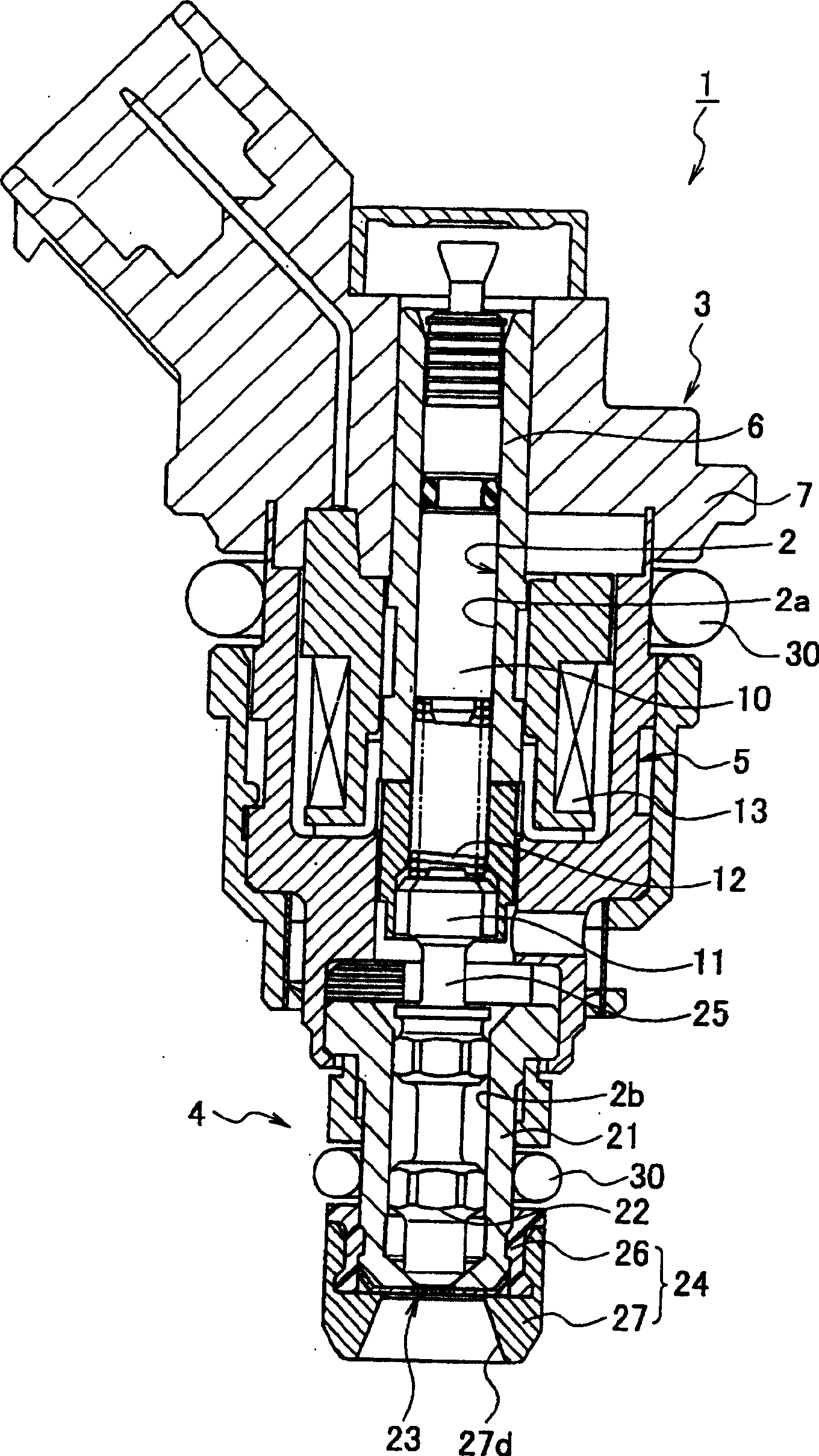
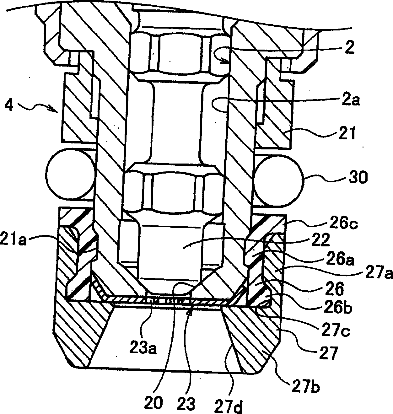
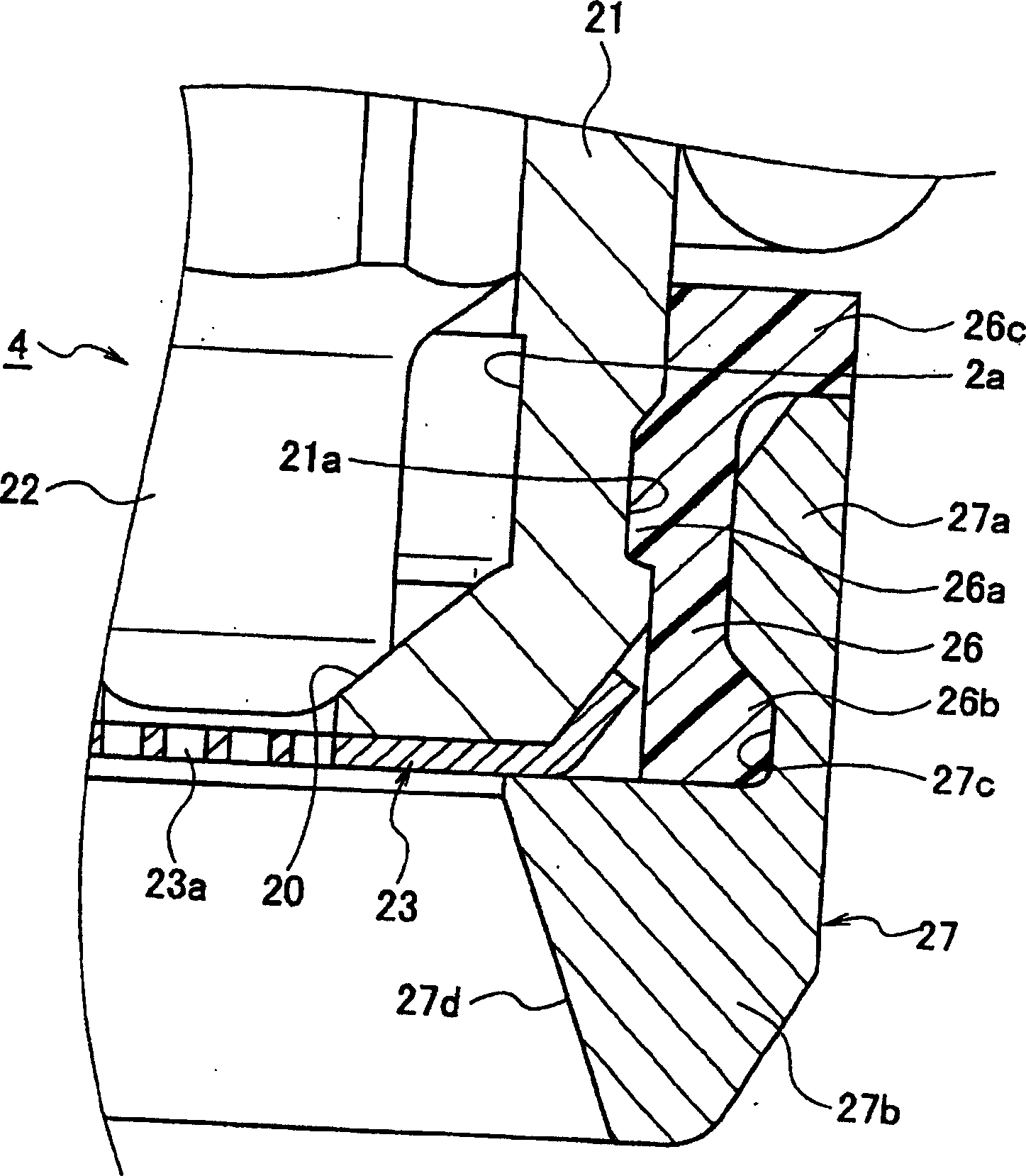
[0026] Figure 1 to Figure 5 represents an embodiment of the present invention, figure 1 is the overall sectional view of the fuel injection valve, figure 2 is a cross-sectional view of the valve mechanism, image 3 It is an enlarged sectional view of the main part of the valve mechanism, Figure 4 is a cross-sectional view of the resin shield part, Figure 5 It is a cross-sectional view of a metal shield component.

[0027] exist figure 1 Among them, the fuel injection valve 1 is provided with a housing 3 in which the upper portion 2a of the fuel flow passage 2 is formed, a valve mechanism 4 for opening and closing the fuel flow passage 2, and the valve mechanism 4 is set between a valve opening position and a valve closing position. Electromagnetic drive for movement5.

[0028] The casing 3 is constructed by assembling a plurality of components such...


PUM


Abstract

The invention discloses a fuel injection valve. The technical problem to be solved by the invention is to provide a fuel injection valve which can prevent dew condensation and icing on a nozzle plate through a protective body. The technical solution to solve the technical problem is a fuel injection valve comprising a valve body (21) with a valve seat surface (20) formed on the wall surface of the fuel flow passage (2), and a valve body (21) arranged in the fuel flow passage (2). A plug (22), a nozzle plate (23) mounted on the front end face of the valve body (21) and having a plurality of nozzle holes (23a), and a nozzle plate (23) mounted on the outer periphery of the valve body (21) to surround the nozzle plate (23) The protective body (24) configured in the manner of the outer circumference of the valve body (21), wherein the protective body (24) is pressed into the outer circumference of the valve body (21) and the locking protrusion (26a) on the inner circumference locks the locking groove of the valve body (21) The resin shield part (26) of (21a), and the peripheral locking protrusion (26b) that is pressed into the outer periphery of the resin shield part (26) and locks the resin shield part (26) in the locking groove part (27c) And it is constituted by a metal shield member (27) having a shield portion (27b) surrounding the outer periphery of the nozzle plate (23).

Description

technical field [0001] The present invention relates to a fuel injection valve that injects a desired amount at a predetermined time on an intake side of an internal combustion engine. Background technique [0002] Various fuel injection valves are proposed in the prior art. Patent Document 1 discloses a fuel injection valve as an example thereof. [0003] The fuel injection valve 100 of the above-mentioned document, such as Figure 6 As shown, the housing 102 that forms the upper part 101a of the fuel flow passage 101 inside, the valve mechanism 103 that is fixed to the lower part of the housing 102 and opens and closes the lower part 101b of the fuel flow passage 101, and the valve mechanism 103 Solenoid actuator (not shown) that moves between open and closed positions. [0004] The valve mechanism 103 includes a valve body 105 that forms the lower portion 101b of the fuel flow passage 101 and forms a valve seat surface 104 on the wall surface of the lower portion 101b o...

Claims


Application Information

Patent Timeline
Patent Type & Authority Applications(China)
IPC IPC(8): F02M61/18F02M51/06F02M51/08F02M53/04
Inventor 新井淳三泽智一山田博
Owner HITACHI LTD
Why Eureka
Try Eureka