
Oil feeder for lubricant in reciprocal movement type compressor

A technology of reciprocating motion and oil supply device, which is applied to the components of pumping devices for elastic fluids, machines/engines, liquid variable capacity machines, etc., and can solve the problems of contamination of refrigerant gas, degradation of lubricating performance, foreign matter, etc. , to prevent contamination of lubricating oil, improve oil supply performance, and prevent wear and tear

Inactive Publication Date: 2005-06-15
LG ELECTRONICS (TIANJIN) APPLIANCES CO LTD
View PDF0 Cites 2 Cited by
  • Summary
  • Abstract
  • Description
  • Claims
  • Application Information

AI Technical Summary

Problems solved by technology

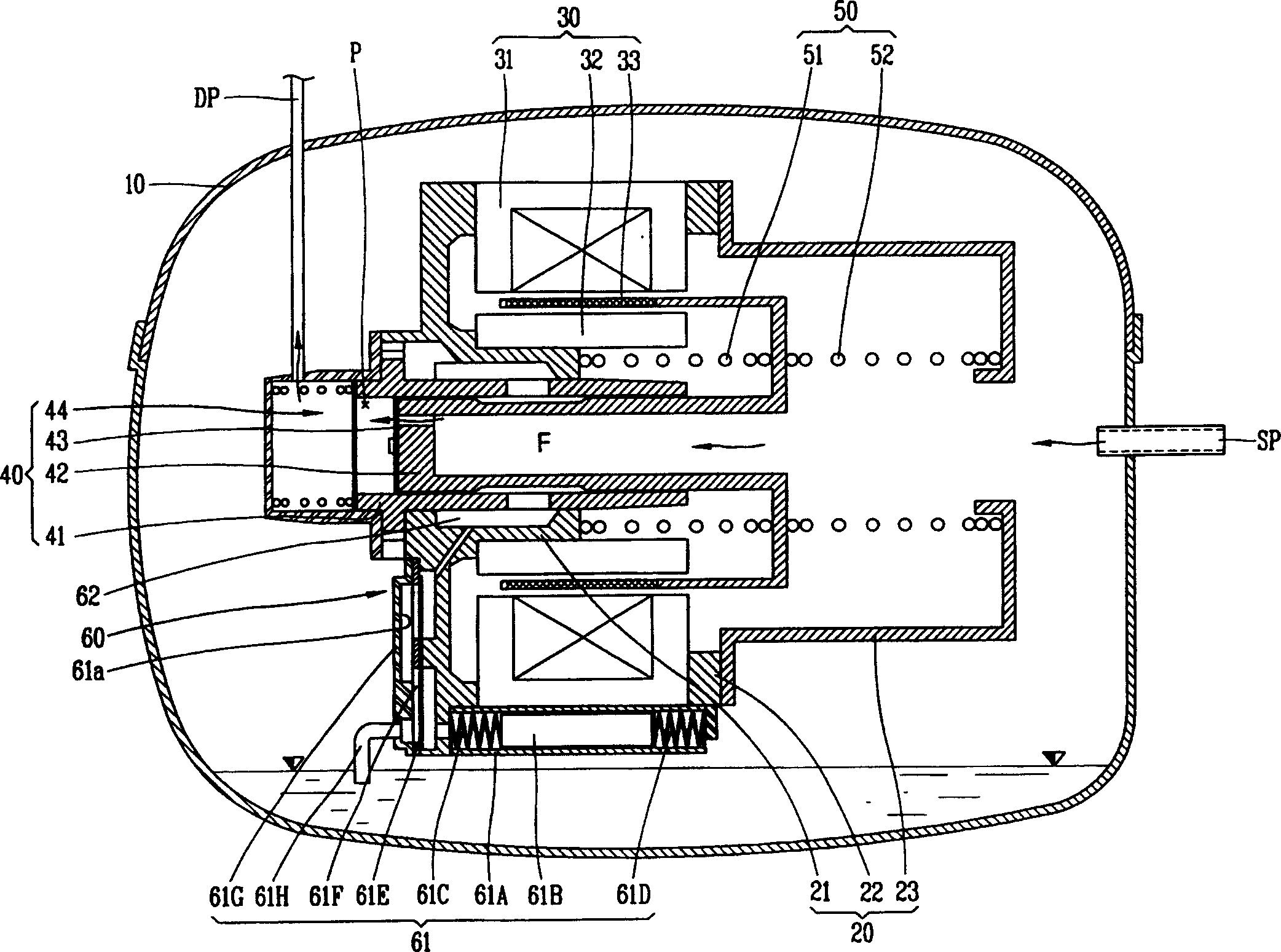
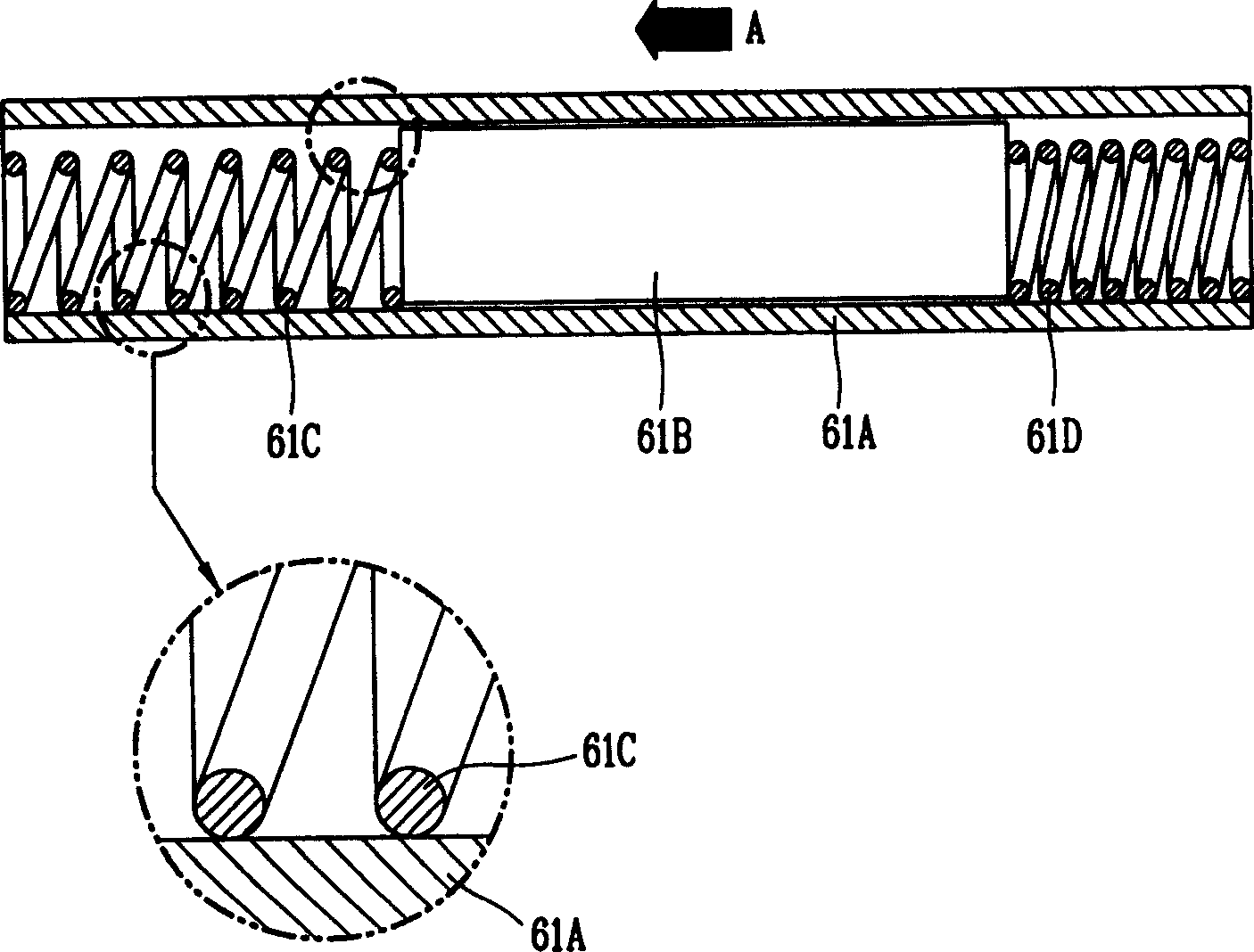
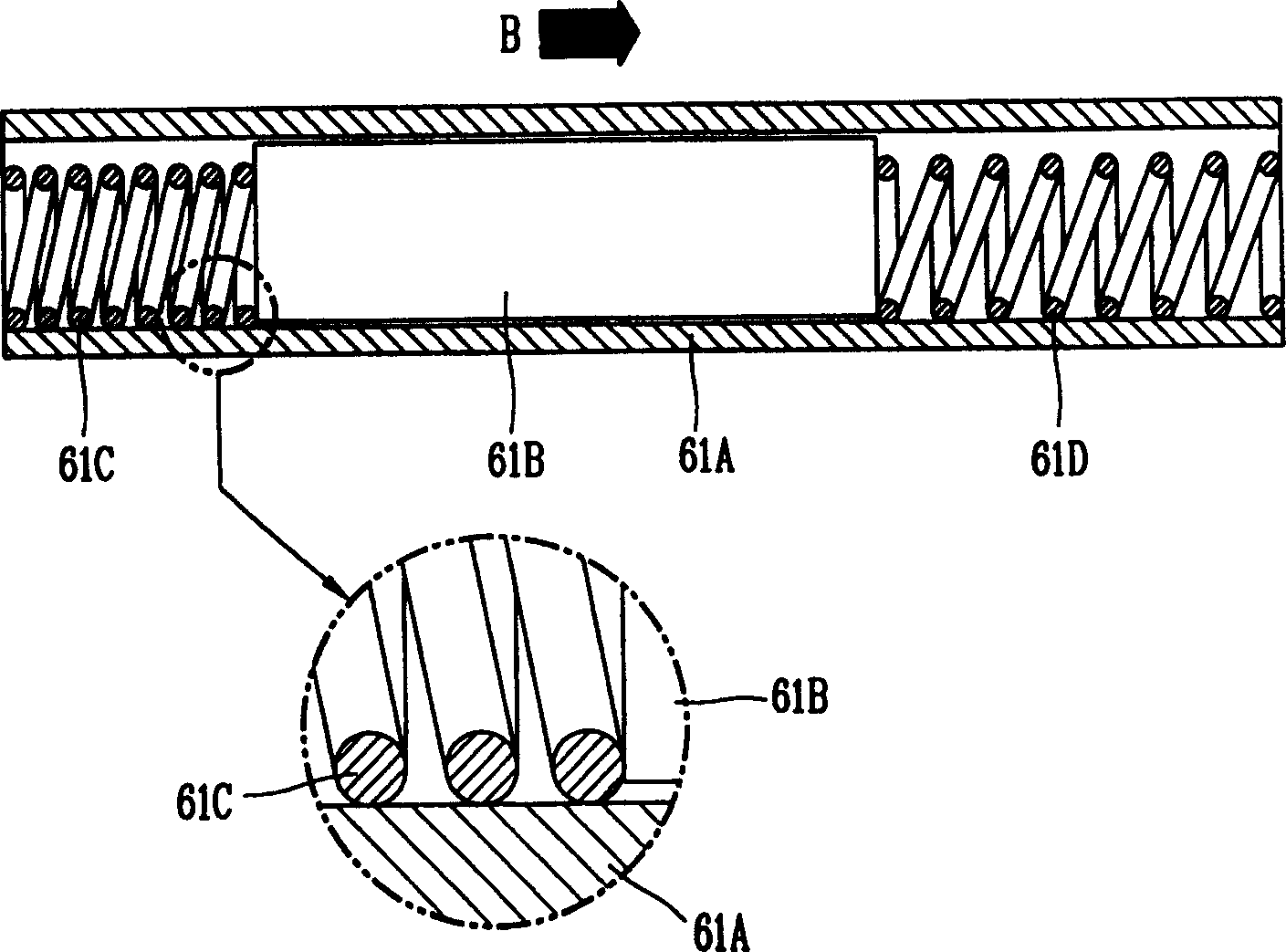
[0015] However, the lubricating oil supply device of the existing reciprocating compressor as described above has the following problems: since the first lubricating oil spring 61C and the second lubricating oil spring 61D are simply attached to both sides of the lubricating oil piston 61B, connected in a way on the side, so the sinking phenomenon will occur
In this case, as shown in Figure 2, with repeated compression and stretching, frictional resistance will be generated between the lubricating oil springs 61C, 61D and the lubricating oil cylinder 61A, so that the lubricating oil piston 61B cannot slide smoothly, resulting in a decrease in lubricating performance.
[0016] In addition, since the ends of the lubricating oil springs 61C and 61D on both sides are easily stuck between the outer rings on both sides of the lubricating oil piston 61B and the lubricating oil cylinder 61A, it will hinder the sliding of the lubricating oil piston 61B and wear the inner surface of the lubricating oil cylinder 61A. surface, resulting in foreign matter
And these foreign substances will be mixed in the lubricating oil and flow into the compression structure, etc., thereby contaminating the refrigerant gas

Method used


Image

  • Oil feeder for lubricant in reciprocal movement type compressor
  • Oil feeder for lubricant in reciprocal movement type compressor
  • Oil feeder for lubricant in reciprocal movement type compressor

Examples


Embodiment Construction

[0036] The lubricating oil supply device for a reciprocating compressor of the present invention will be described in detail below with reference to the examples shown in the accompanying drawings.

[0037] image 3 is a longitudinal sectional view of an example of the reciprocating compressor of the present invention, Figure 4a and Figure 4b It is a longitudinal sectional view of the operating state of the lubricating oil supply device of the present invention, Figure 5 It is a longitudinal sectional view of a modified example of the lubricating oil supply device of the present invention.

[0038] As shown in the accompanying drawings, the reciprocating compressor equipped with the lubricating oil supply device of the present invention is composed of the following parts, namely: the casing 10, which contains a certain amount of lubricating oil; the frame assembly 20, which maintains a certain degree of elasticity. Installed inside the casing 10; the reciprocating motor ...


PUM


Abstract

The invention relates to a lubricating oil supply device of reciprocal compressor. It is characterized by that on two side surfaces of the lub oil piston in said reciprocal compressor a spring fixing portion is respectively formed, the above-mentioned lubricating oil spring can be placed and fixed on the above-mentioned spring fixing portion, so that the above-mentioned lub oil spring always can be relained in the orignial position, and said structure can make the lub oil spring be repeatedly comperssed and extended on the fixed position always so as to can raise oil supply performance.

Description

technical field [0001] The present invention relates to a lubricating oil supply device (APPARATUS FOR SUPPLYING OIL OF RECIPROCATING COMPRESSOR) capable of pumping lubricating oil in a reciprocating compressor. The lubricating oil supply device of the reciprocating compressor: it can prevent the lubricating oil spring from contacting the lubricating oil cylinder, thus improving the oil supply performance and reducing wear. Background technique [0002] Generally, reciprocating compressors draw in and compress gas through the linear motion of a piston. Such reciprocating compressors can be roughly divided into the following methods, namely: converting the rotational motion of the drive motor into the reciprocating motion of the piston, thereby sucking and compressing the gas; A reciprocating motion is also performed to suck in and compress the gas. [0003] figure 1 It is a vertical cross-sectional view of an example of a conventional reciprocating compressor of the latte...

Claims


Application Information

Patent Timeline
Patent Type & Authority Applications(China)
IPC IPC(8): F04B17/03F04B39/02F04B53/18
Inventor 玄成烈
Owner LG ELECTRONICS (TIANJIN) APPLIANCES CO LTD
Learn More