

Method of making substrate for flexible circuit board
一种挠性电路板、基底的技术,应用在电路基板材料、印刷电路、印刷电路等方向,能够解决实际尺寸与设计尺寸改变等问题,达到抑制尺寸变化的效果
- Summary
- Abstract
- Description
- Claims
- Application Information
AI Technical Summary
Problems solved by technology
Method used
Image

Examples
Embodiment 1-3 and comparative example 1-2
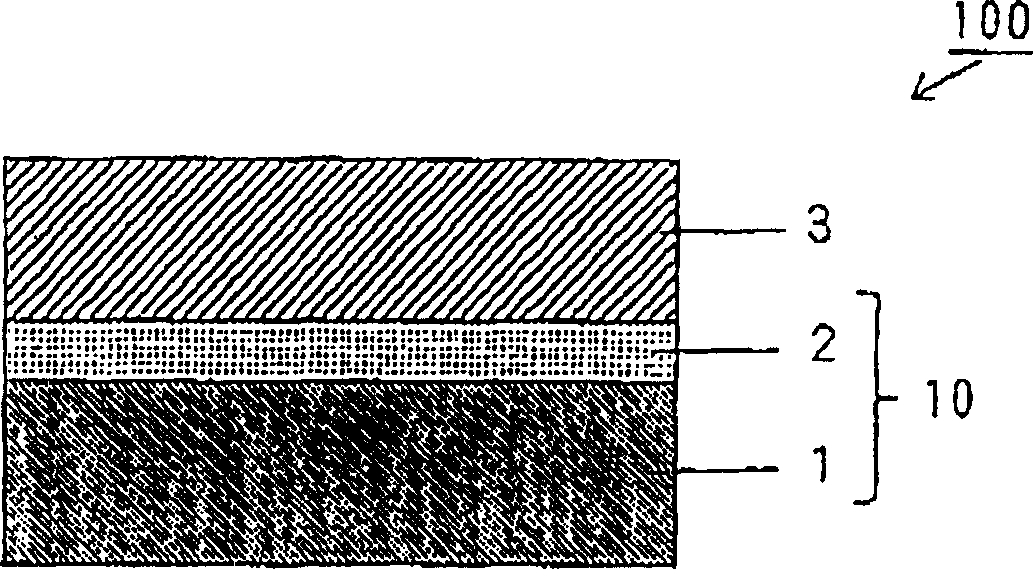
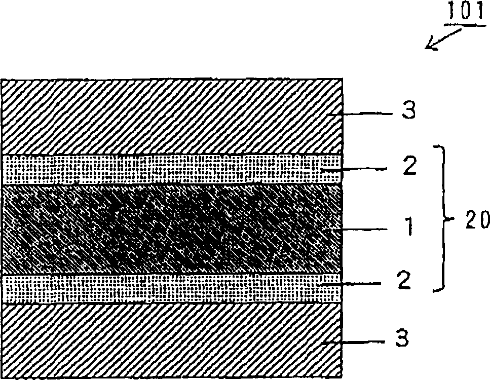
[0063] The flexible circuit substrates of Examples 1-3 were produced according to the first or second embodiment, and the flexible circuit substrates of Comparative Examples 1-2 were also produced. The metal foil 3 of the produced flexible circuit substrate was etched, and then the dimensional change of the flexible printed wiring board was evaluated.
[0064] In Example 3 and Comparative Example 2, the substrate 100 for a single-sided flexible circuit board was used. In Examples 1-2 and Comparative Example 1, the substrate 101 for a double-sided flexible circuit board was used.
[0065] Table 1 shows the properties of the insulating layer 1 in each of the substrate 100 for a single-sided flexible circuit board and the substrate 101 for a double-sided flexible circuit board used in Examples 1-3 and Comparative Examples 1-2. Material and thickness (μm).
[0066] Table 2 shows the adhesive layer 2 of each of the substrate 100 for a single-sided flexible circuit board and the s...
PUM
| Property | Measurement | Unit |
|---|---|---|
| tensile modulus | aaaaa | aaaaa |
| glass transition temperature | aaaaa | aaaaa |
Abstract
Description
Claims
Application Information