Dynamic reconfigurable multi-granularity optical buffer for all-optical switching network
An optical buffer, multi-granularity technology, applied in the field of optical communication, can solve the problems of crosstalk, polarization sensitivity, large insertion loss, etc.
- Summary
- Abstract
- Description
- Claims
- Application Information
AI Technical Summary
Problems solved by technology
Method used
Image
Examples
Embodiment 1
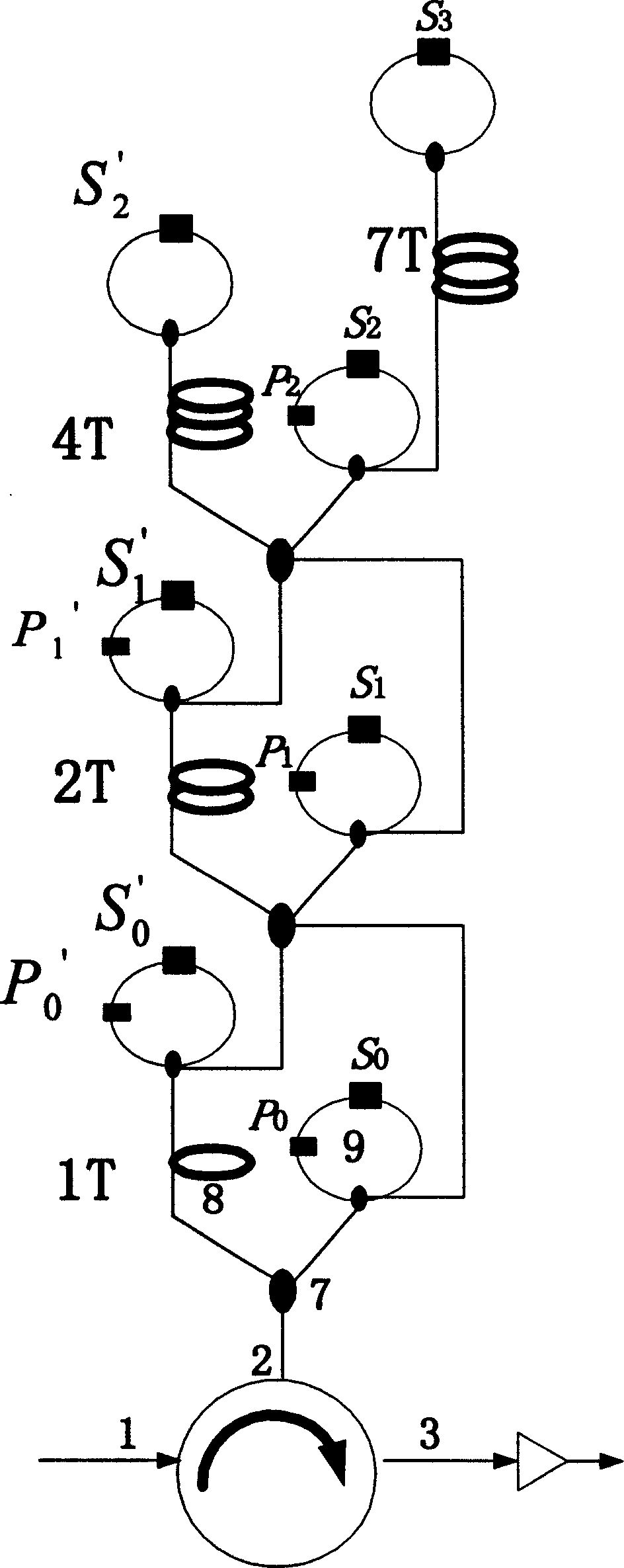
[0028] Embodiment 1: It is intended to delay the buffering of data packets in the optical buffer to 9750×2T.
[0029] The data packet cache delay in the 4-level delay line tree is 9×1000×2T; the delay in the 3-level delay line tree cache is 7×100×2T; the delay in the 2-level delay line tree cache is 5×10×2T; The cache delay is 0 at the level 1 delay line tree. The process that the data packet goes through in the buffer is as attached Figure 5 As indicated by the dotted line, the steps are as follows:
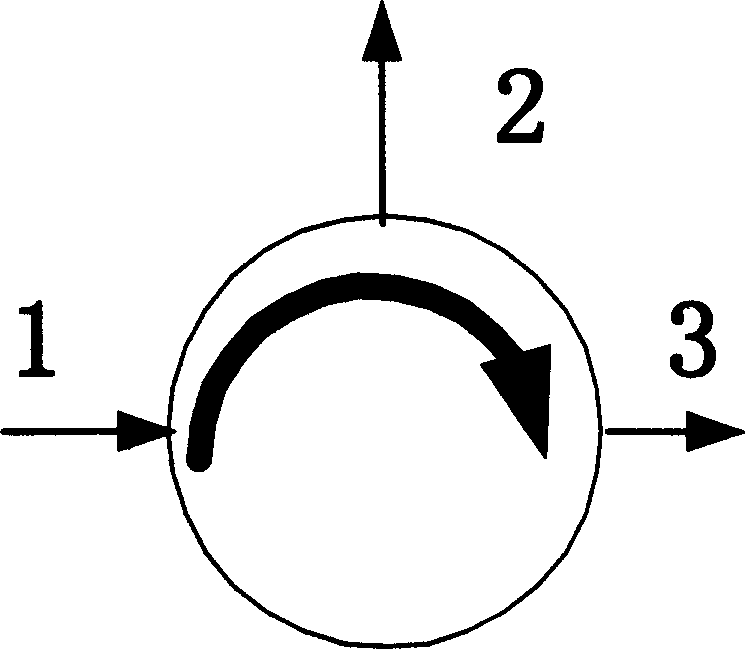
[0030] (1) The data packet is input from the circulator port (1), and first enters the fourth-stage delay line tree through the port (2). At this time, the gain switch S in the delay line tree is 0 , S 1 ', S 2 , S 3 On, the phase shifter P 0 , P 1 ', P 2 On, other gain switches and phase shifters off. The data packet passes through the optical delay line 2000T, then passes through the optical delay line 7000T, passes through the delay line 7000T after returning from t...
Embodiment 2
[0034] Embodiment 2: It is intended to delay the buffering of data packets in the optical buffer to 123×2T.
[0035] The delay of the data packet in the 4-level delay line tree cache is zero; the delay in the 3-level delay line tree cache is 1×100×2T; the delay in the 2-level delay line tree cache is 2×10×2T; the delay in the 1-level delay The line tree cache delay is 3×2T. The process that the data packet goes through in the buffer is as attached Figure 6 As indicated by the dotted line, the steps are as follows:
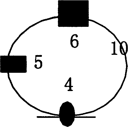
[0036] (1) The data packet is input from the circulator port (1), and first enters the fourth-stage delay line tree through the port (2). At this time, the gain switch in the delay line tree is only the gain switch S 0 On, other gain switches and phase shifters off. The data packet is directly returned from the TOAD ring to the circulator port (2), output from the port (3), and after being amplified, enters the next stage of the delay line tree. At this time, ...
PUM
 Abstract
Description
Claims
Application Information
 - R&D
- Intellectual Property
- Life Sciences
- Materials
- Tech Scout
- Unparalleled Data Quality
- Higher Quality Content
- 60% Fewer Hallucinations
Browse by: Latest US Patents, China's latest patents, Technical Efficacy Thesaurus, Application Domain, Technology Topic, Popular Technical Reports.
© 2025 PatSnap. All rights reserved.Legal|Privacy policy|Modern Slavery Act Transparency Statement|Sitemap|About US| Contact US: help@patsnap.com


