Active electroluminescent display and power supply circuit therefor

A power supply circuit, electroluminescence technology, applied in the direction of electroluminescence light source, electric light source, light source, etc., can solve problems such as change

Active Publication Date: 2005-06-29
AU OPTRONICS CORP
View PDF0 Cites 11 Cited by
  • Summary
  • Abstract
  • Description
  • Claims
  • Application Information

AI Technical Summary

Problems solved by technology

[0008] In view of this, the object of the present invention is to provide an active electroluminescence display and its power supply circuit, by using the voltage on the electrode as the feedback voltage, to solve the problem of the voltage drop on the power input line and the power consumption of the display panel. The problem of changing and changing, so that the bias voltage input to the pixel is more stable

Method used


Image

  • Active electroluminescent display and power supply circuit therefor
  • Active electroluminescent display and power supply circuit therefor
  • Active electroluminescent display and power supply circuit therefor

Examples


Embodiment Construction

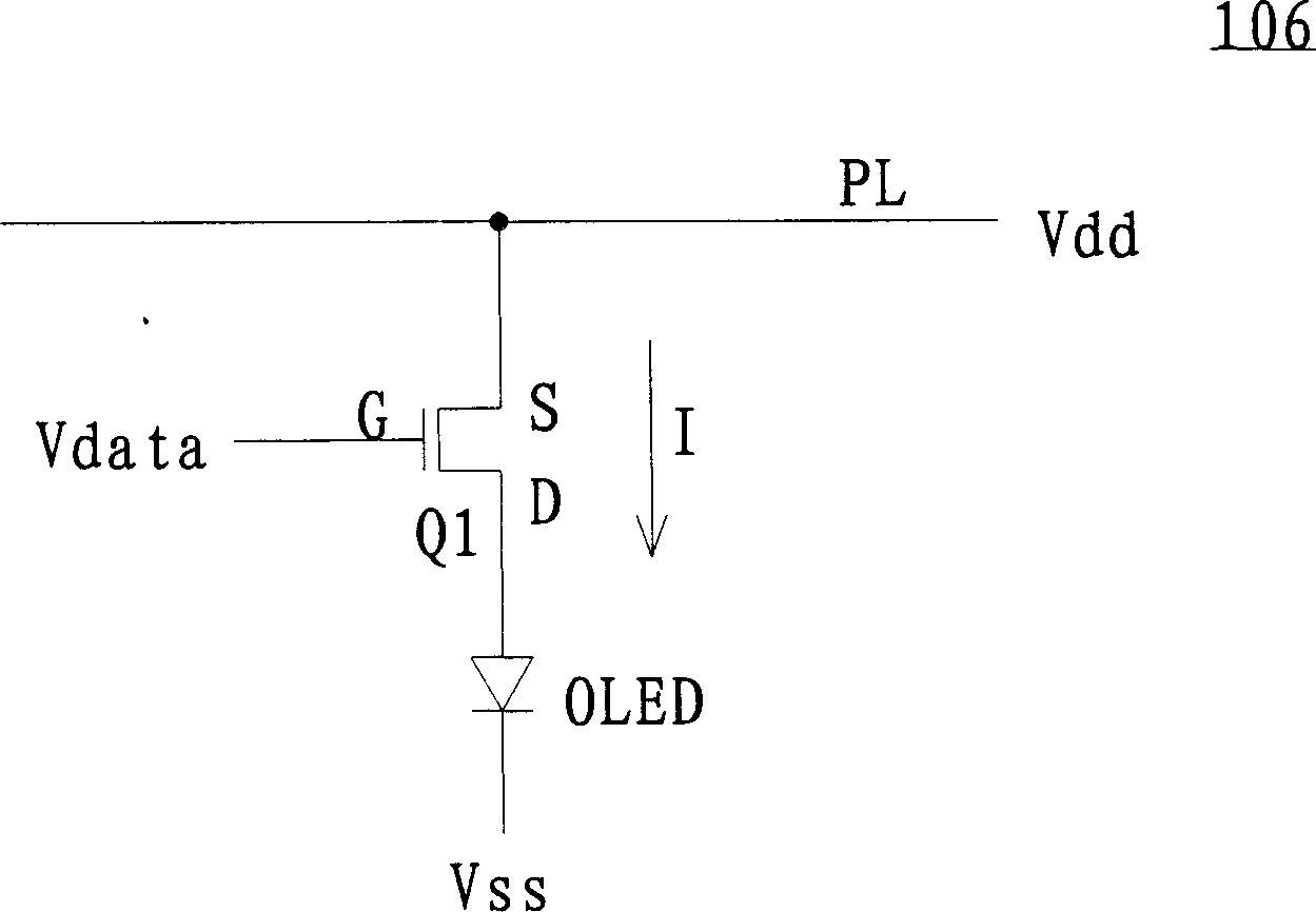
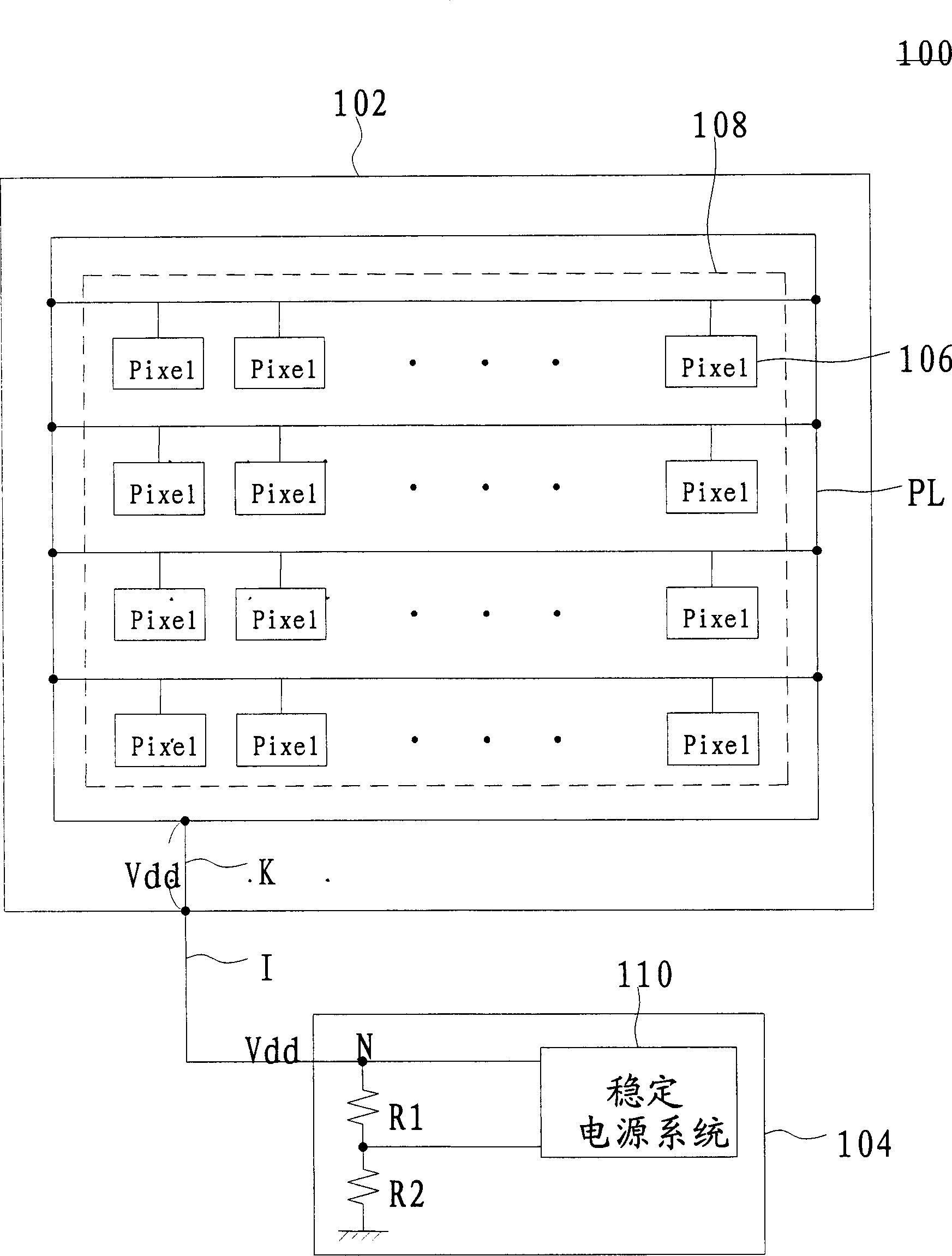
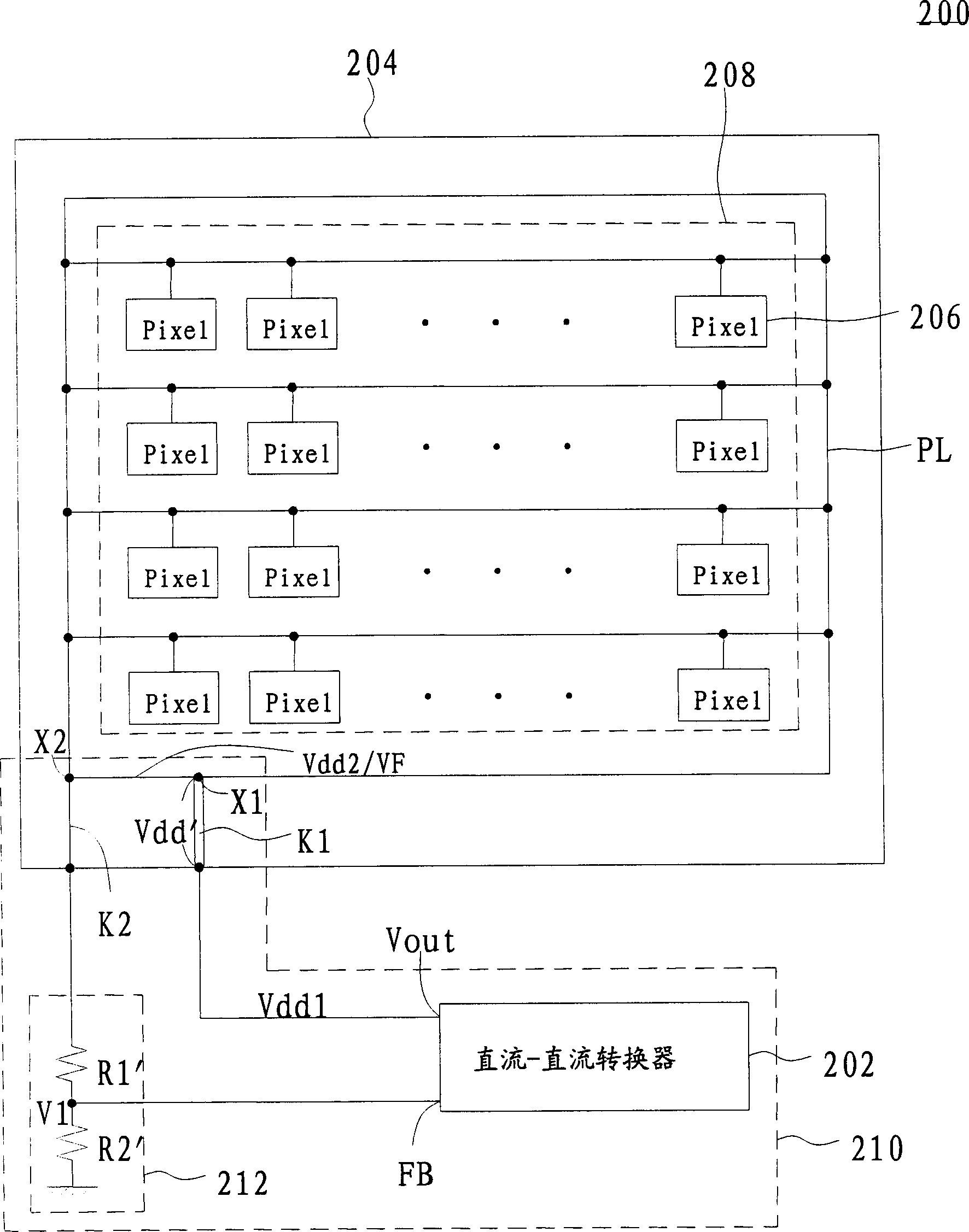
[0014] The traditional approach can only ensure that the bias voltage output by the DC-DC converter remains stable. However, since the active electroluminescent components, such as organic light emitting diodes, the part of the power input line of the display on the substrate is formed of polysilicon semiconductor material, it has a larger resistance value than ordinary metal lines. Therefore, when the bias voltage is from the DC-DC converter, through the metal wire and then through the power input line to the electrode, a non-negligible voltage drop will occur. This voltage drop will cause the bias voltage on the electrode to be lower than the set value, so that the LED pixel cannot achieve the predetermined luminous brightness. Moreover, the fluctuation range of the bias voltage will increase with the increase of the power consumption of the pixel array, so that the luminance of the light-emitting diode becomes very unsatisfactory, resulting in the phenomenon that the bright...


PUM


Abstract

An active electro-excited luminous display, such as an organic luminous display includes a display panel and a power supply circuit. The panel contains a pixel tuple and an electrode driving the pixel tuple, in which, the electrode is connected with the pixel tuple and has the first connection point and a second connection point. The power supply circuit includes a feed back circuit, a supply system, a supply input line and a regulated reference line. The power supply system has an output end and a feedback end to output bias voltage at the output end, one end of the supply input line is connected with the first connection point, the other end receives the bias voltage, one end of the regulated reference line is connected with the second connection point, the other end outputs feed back voltage.

Description

technical field [0001] The present invention relates to an active electroluminescence display, and in particular to a power supply circuit for driving an active electroluminescence display. Background technique [0002] Please refer to figure 1 , which is a structural schematic diagram of a light-emitting diode pixel. From figure 1 It can be seen that the source S of the TFT Q1 in the LED pixel 106 receives the bias voltage Vdd through the electrode PL, its drain D is coupled to the anode of the LED OLED, and its gate G receives the voltage Vdata. The cathode of the light emitting diode OLED is coupled to a fixed voltage, such as the bias voltage Vss. drive circuit (not shown in figure 1 Middle) According to different grayscale values, the voltage Vdata generates a corresponding voltage, so as to control the voltage difference Vsg between the gate G and the source S of the thin film transistor Q1. The magnitude of the current I flowing through the organic light emitting...

Claims


Application Information

Patent Timeline
Patent Type & Authority Applications(China)
IPC IPC(8): G02F1/133G09G3/30H05B33/12H05B44/00
CPCY02B20/30
Inventor 胡硕修
Owner AU OPTRONICS CORP
Why Eureka
Try Eureka