
Dismountable combined particle filling machine

A combined, filling machine technology, applied in loading/unloading, transportation and packaging, chemical instruments and methods, etc., can solve problems such as slow speed, non-disassembly, and rework

Active Publication Date: 2005-07-06
中国石油化工股份有限公司北京燕山分公司研究院
View PDF0 Cites 7 Cited by
  • Summary
  • Abstract
  • Description
  • Claims
  • Application Information

AI Technical Summary

Problems solved by technology

[0003] Domestic silver catalyst filling was initially filled manually with a distributor, but the speed was slow. At present, it has been replaced by manual filling in bags and tubes. This kind of filling has problems such as easy bridging, uneven pressure drop, more rework, and low efficiency.
There are also two foreign silver catalyst filling methods. One is the distributor method. This method requires a part of the new catalyst to be loaded into the reactor and then sucked out so that it cannot be reused. The sucked out catalyst accounts for about 9% of the filling volume, causing a lot of waste, and the filling speed is slow, basically do not use this method now
At present, catalyst suppliers generally provide machine filling services. Due to the large size and weight of various filling machines at present, and they cannot be disassembled, they cannot enter the reactor, and can only be connected outside the reactor through a hose to enter the reaction If the hose is too long, the slope will change greatly, which will easily cause the silver catalyst to be blocked and bridged in the hose due to poor fluidity, thus affecting the loading effect of the catalyst.

Method used


Image

  • Dismountable combined particle filling machine
  • Dismountable combined particle filling machine
  • Dismountable combined particle filling machine

Examples


Embodiment Construction

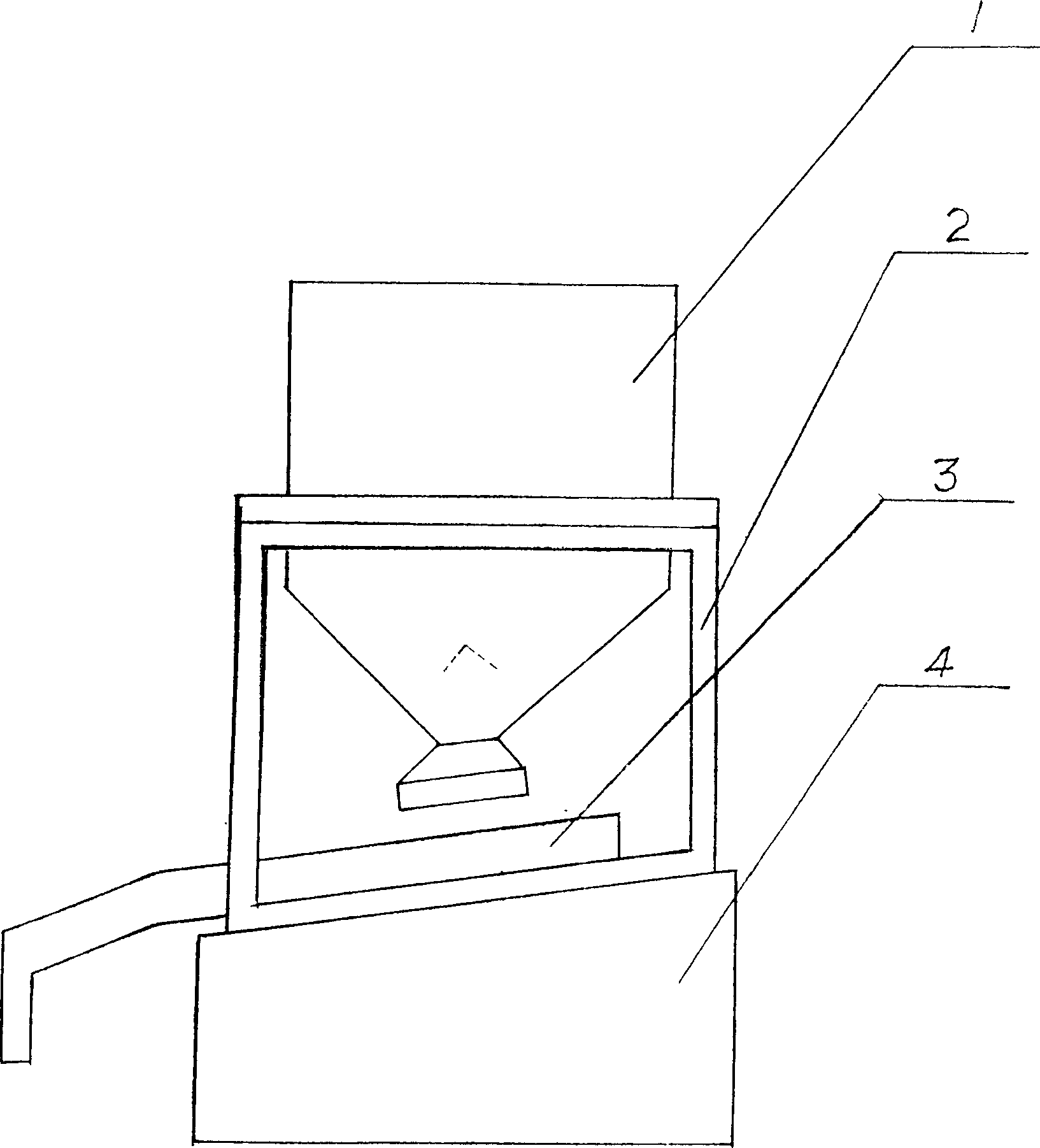
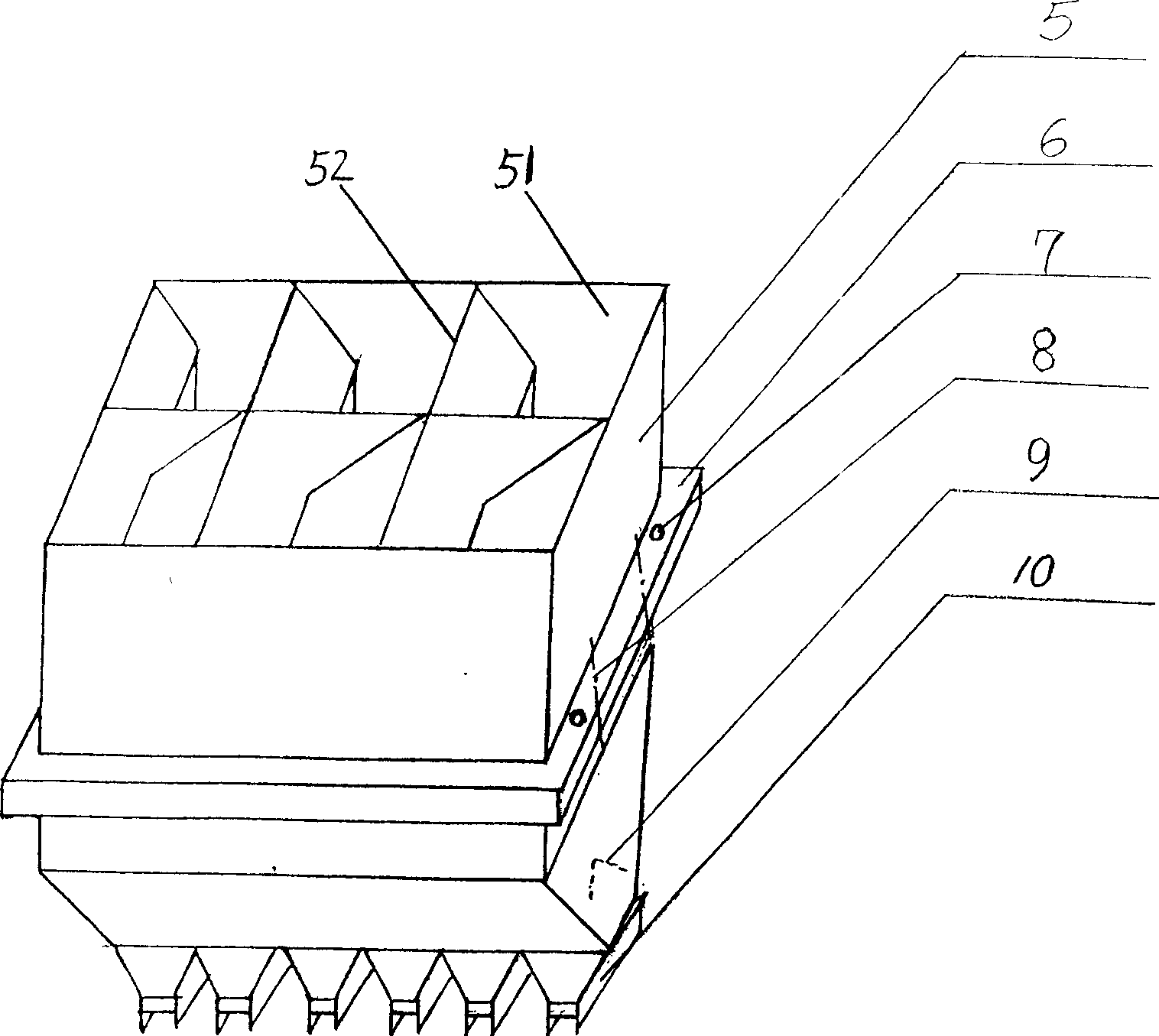
[0020] Such as figure 1 As shown, the present invention discloses a detachable combined particle filling machine, which includes: a hopper 1 and a material conveyor 3, and the granular material loaded into the hopper 1 is transported by the material conveyor 3 Into the target place, wherein, the hopper 1 is supported above a base 4 by a bracket 2, the material conveyor 3 is located on the base 4 and below the discharge port 10 of the hopper 1, the material conveyor 3 can be placed on a Driven by the power transmission system, it reciprocates on the base 4 .

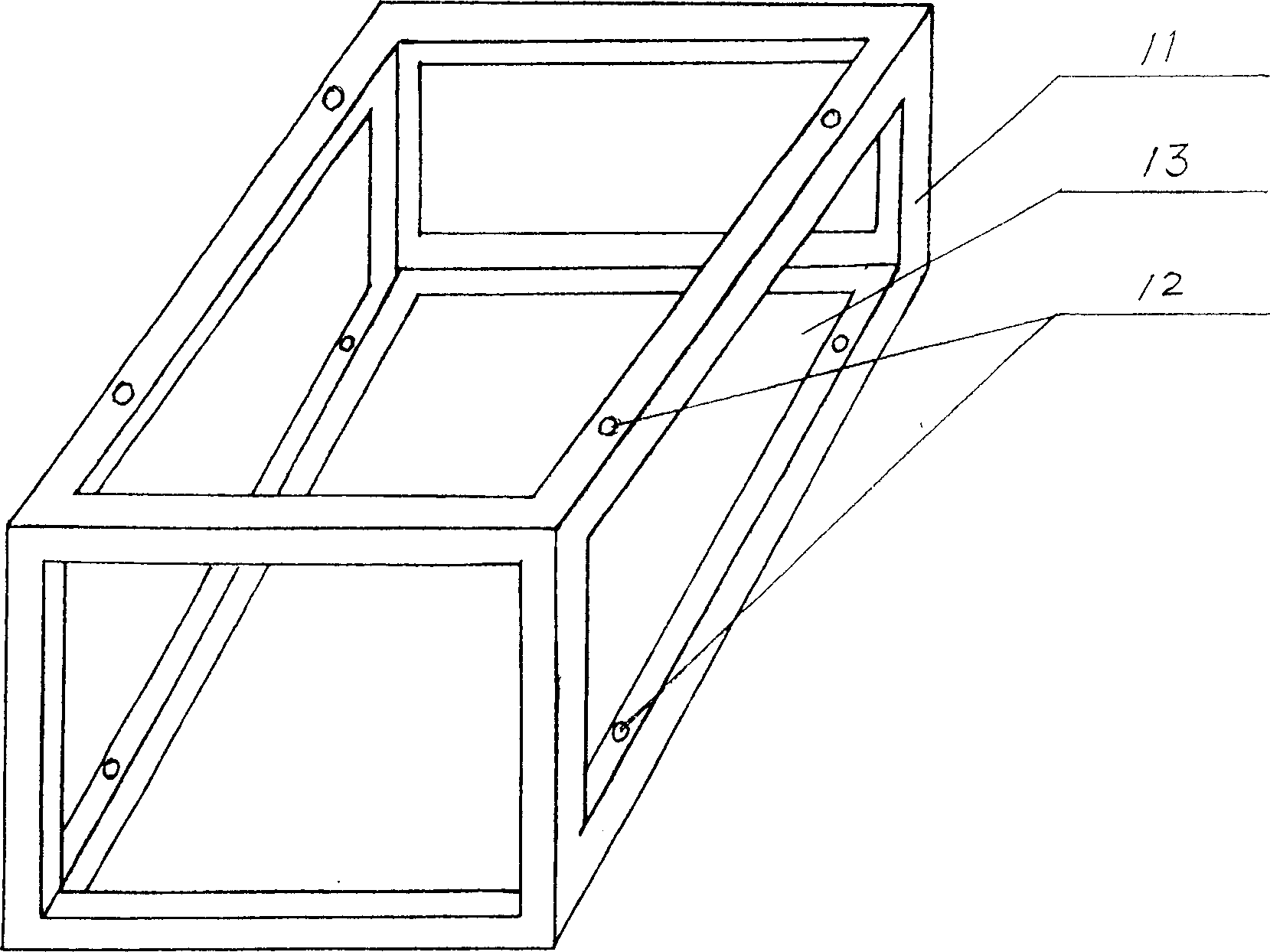
[0021] According to an embodiment of the present invention, such as Figure 4 and 5 As shown, the base 4 is provided with a guide groove 21, and the corresponding position on the material conveyor 3 is provided with a slider 17. 21, so that the material conveyor 3 reciprocates on the base 4. The guide slots 21 can be arranged on both sides of the base 4 , and the sliders 17 are correspondingly arranged on both sides o...


PUM


Abstract

This invention relates to disassemble composite particles filling machine, which comprises the following: materials chute and material transmission device to send the particles in the chute to the destiny place, wherein the chute is supported by one rack above one base socket; the material transmission device is located on the base socket under the material exit mouth of chute; the transmission device can move back and forth by one dynamic driving system on the said base socket.

Description

technical field [0001] The invention relates to a detachable combined particle filling machine, in particular to a detachable combined particle filling machine for silver catalyst particles. Background technique [0002] Silver catalyst is an expensive product with huge associated economic benefits. The process of filling it into the reaction tube during use is extremely important, because whether the catalyst bed is bridged and whether the bed height is consistent will affect the bulk density of the bed and the uniformity of pressure drop, thereby affecting the efficiency of the catalyst and device safety. This not only affects the reputation of catalyst suppliers, but also affects the economic benefits of catalyst use, so both parties attach great importance to the work of catalyst loading. [0003] Domestic silver catalyst filling was first carried out manually with a sparger, but the speed was slow. At present, it has been replaced by manual filling in bags and tubes. ...

Claims


Application Information

Patent Timeline
IPC IPC(8): B01J8/02B65G65/32
Inventor 尹国海张克万曰亮高英杰
Owner 中国石油化工股份有限公司北京燕山分公司研究院
Learn More