
Electrostatic chuck, substrate support, clamp and electrode structure and producing method thereof

An electrostatic chuck and substrate technology, which is applied in semiconductor/solid-state device manufacturing, circuits, electrical components, etc., can solve problems such as uneven plasma density, plasma cannot be uniformly generated, and electrode temperature increases.

Inactive Publication Date: 2005-07-13
ADVANCED DISPLAY PROCESS ENG
View PDF1 Cites 11 Cited by
  • Summary
  • Abstract
  • Description
  • Claims
  • Application Information

AI Technical Summary

Problems solved by technology

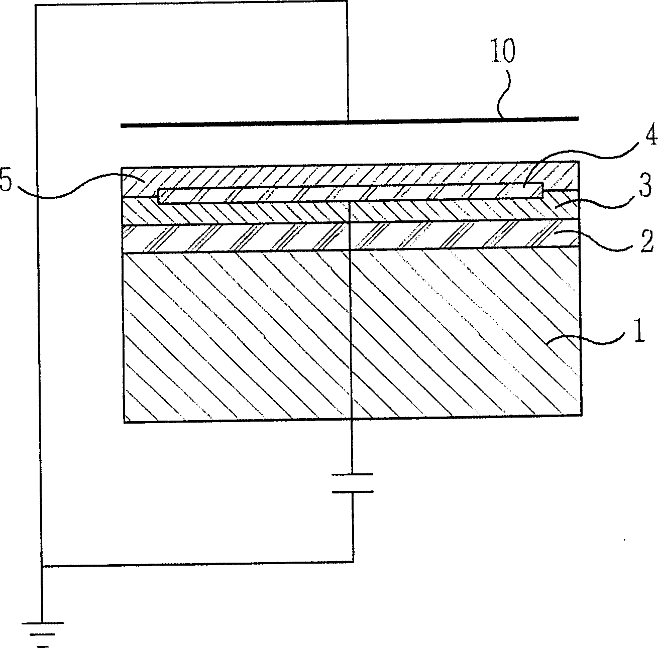
[0005] However, this conventional electrostatic chuck has the disadvantage that particles appear on the substrate 10 when the electrostatic chuck comes into contact with the substrate 10, and when the entire surface of the substrate comes into contact with the electrostatic chuck, there is Difficulty maintaining substrate flatness
[0008] However, in this case, there is a problem that it is difficult to prepare and mass-produce embossed planes
Therefore, according to the power characteristics of the high-frequency signal propagating along the surface of the conductor, the roughness or unevenness of the conductor surface has a great influence on the power transfer of the high-frequency signal, which can cause power loss of the high-frequency signal
In addition, power loss in the power transfer process of high-frequency signals is converted into thermal energy, which leads to an increase in electrode temperature
[0013] Therefore, conventional electrodes have the following problems: power loss of high-frequency signals, increase in electrode temperature due to power loss, and electrode damage due to increase in electrode temperature
[0014] In addition, recently, as substrates processed by plasma processing equipment become larger, there has been a problem that different parts of the substrate experience different levels of treatment
Since the power of the high-frequency signal is not uniformly applied to the conventional electrodes, the plasma cannot be uniformly generated
Also, as the area of ​​the electrode increases and thus the difference in the uniformity of the plasma between the center portion and the edge portion of the electrode increases, there arises a problem of unevenness in etching or deposition of the substrate to be processed.

Method used


Image

  • Electrostatic chuck, substrate support, clamp and electrode structure and producing method thereof
  • Electrostatic chuck, substrate support, clamp and electrode structure and producing method thereof
  • Electrostatic chuck, substrate support, clamp and electrode structure and producing method thereof

Examples


Embodiment Construction

[0037] Preferred embodiments of the present invention will be described below with reference to the accompanying drawings.

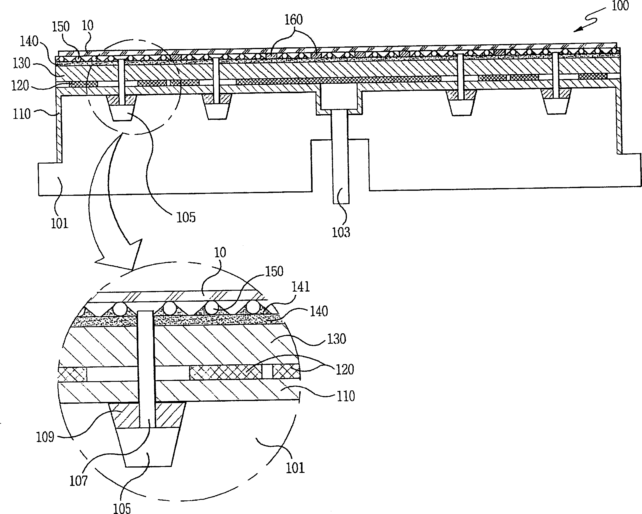
[0038] refer to image 3, the electrostatic chuck 100 according to the embodiment of the present invention includes: a supporting component 101; a lower insulating layer 110, which is formed by an insulating material coated on the supporting component 101; a plurality of electrode patterns, which are attached to the lower insulating layer 110; an insulating layer 130 formed of an insulating material coated on the electrode pattern; a junction layer formed of a junction material coated on the upper insulating layer 130; a plurality of supporting balls arranged and bonded to the junction layer 140; and a plurality of A leakage prevention dam 160 is fixedly arranged between the plurality of support balls.

[0039] The support member 101 has a flat top surface and holes formed at the upper and lower sides of the center of the support member 101 . Electrode...


PUM


Abstract

Disclosed is an electrostatic chuck that makes point contact with a substrate by using a plurality of support balls to minimize the contact area so as to prevent contact damage to the semiconductor substrate; a substrate support; A fixture for securing the sheet; and a method of manufacturing the same. In addition, an electrode structure used as an upper electrode or a lower electrode provided in a plasma processing apparatus and a method of manufacturing the same are disclosed.

Description

technical field [0001] The present invention relates to an electrostatic chuck which makes point contact with a substrate: using a plurality of support balls to minimize the contact area in order to prevent contact damage to the semiconductor substrate; a substrate support; A jig for fixing a substrate; and a manufacturing method thereof. [0002] In addition, the present invention relates to a structure of an electrode provided in a plasma processing apparatus and a method of manufacturing the same, and more particularly, to an electrode for preventing high-frequency power loss and forming uniform plasma by : forming a metal layer on the overall area between an electrode base material and an insulating layer or forming a metal layer with a specific shape between the electrode base material and the insulating layer, and a manufacturing method thereof. Background technique [0003] In recent years, there has been an urgent need to improve positioning accuracy when patterning...

Claims


Application Information

Patent Timeline
Patent Type & Authority Applications(China)
IPC IPC(8): H01L21/68
Inventor 许光虎崔浚泳李哲源曹生贤安成一
Owner ADVANCED DISPLAY PROCESS ENG
Learn More