Magnetizing method and device for permanent-magnet motor

A permanent magnet and motor technology, which is applied to electromechanical devices, manufacturing motor generators, and motor components, etc., can solve the problems of increasing temperature rise, inability to perform alignment, large equipment, etc., and achieve stable performance and stable magnetization effect.

Active Publication Date: 2005-07-13
PANASONIC CORP
View PDF2 Cites 6 Cited by
  • Summary
  • Abstract
  • Description
  • Claims
  • Application Information

AI Technical Summary

Problems solved by technology

[0010] However, when alignment is performed using jigs, visual inspection, and image processing, there is a problem that alignment cannot be performed if the positional relationship between the stator and rotor inside the compressor is in a structure that cannot be seen.
[0011] In addition, when energizing for alignment, the rotor must be moved by energizing the winding, so the amount of current energizing the winding increases.
In addition, in this method, in order to obtain the accuracy necessary for position integration, it is necessary to further increase the current value
In this way, since the amount of current increases, the temperature rise increases, and there is also a problem that a large-capacity device is required, and a large-scale device is required.
[0012] In addition, although the method disclosed in Patent Document 1 has the advantage of integrating the magnetization position even if the internal structure of the compressor cannot be seen, there is a change in the inductance value caused by the rotation of the rotor, which affects the resolution of the equipment that measures it. When the value is not large, the error included in the detection of the rotor angle indicating the peak value becomes large.
As a result, when the change in inductance value is small, the optimum magnetization position cannot be detected, and good magnetization cannot be performed.

Method used


Image

  • Magnetizing method and device for permanent-magnet motor
  • Magnetizing method and device for permanent-magnet motor
  • Magnetizing method and device for permanent-magnet motor

Examples


Embodiment Construction

[0036] Hereinafter, referring to the accompanying drawings, the embodiments of the present invention will be described in detail.

[0037]

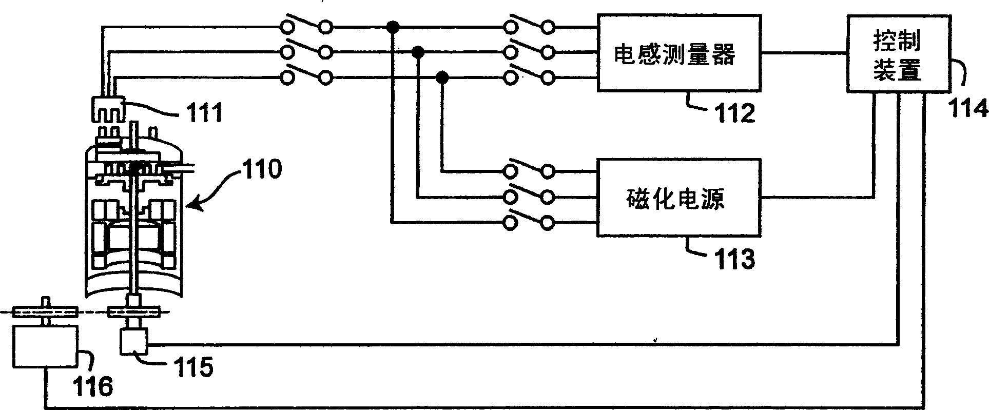
[0038] figure 1 It is a block diagram showing the configuration of an apparatus for implementing the magnetization method according to the present invention. In the compressor motor part 110, the three-phase winding of the stator of the permanent magnet type motor magnetized by the method related to the present invention is connected with the inductance measurement unit—the inductance measuring device 112 and the magnetization unit—the magnetization power supply 113 through the electrode 111 . With a plurality of switches appropriately arranged therein, current can be made to flow through a desired phase. The switch can also be switched by the control unit—the control device 114 .

[0039]In addition, the inductance measuring device 112 and the magnetizing power source 113 are connected to the control device 114 , and the inductance ...


PUM


Abstract

The magnetization method of the permanent magnet type motor related to the present invention includes: the first to the third inductance measurement steps (S201 to S203) of measuring the inductance involved in the combination of the two phases in the three-phase winding; according to the three inductance measurement values ​​( 1st to 3rd inductance measurement values), the step of specifying the relative positional relationship between the rotor and the stator (S205); A step of magnetizing the unmagnetized magnetizable member (S205 to S210). Therefore, even if the internal structure of the compressor cannot be seen, the relative position of the rotor and the stator can be accurately aligned with a small device, and the magnetization method and device of the permanent magnet type motor can be magnetized without magnetization.

Description

technical field [0001] The invention relates to a permanent magnet motor, in particular to a magnetization method and device for its rotor. Background technique [0002] A conventional permanent magnet motor includes a stator that generates a rotating magnetic field by applying current to a winding mounted on a stator core made of a magnetic material, and a rotor that has permanent magnets that are rotatably disposed in the stator core. From the viewpoint of energy saving, permanent magnet motors are widely used, for example, as motors for compressors of air conditioners. [0003] When the permanent magnet type motor is assembled, when the rotor is inserted into the stator, the magnetic parts of the rotor are magnetized, and under the action of its strong magnetic force, the rotor is often attracted to the inner peripheral surface of the stator core and becomes immovable. The locked state makes it difficult to insert the rotor into the stator. [0004] For this reason, the...

Claims


Application Information

Patent Timeline
Patent Type & Authority Applications(China)
IPC IPC(8): H02K1/27H02K15/03
CPCH02K1/276H02K1/28H02K11/215H02K15/03
Inventor 村上秀树福原弘之
Owner PANASONIC CORP
Why Eureka
Try Eureka