Resonant power converter and method for wireless radio frequency transmission
A power converter, resonator technology, applied in the field of radio frequency signals
- Summary
- Abstract
- Description
- Claims
- Application Information
AI Technical Summary
Problems solved by technology
Method used
Image
Examples
example 1
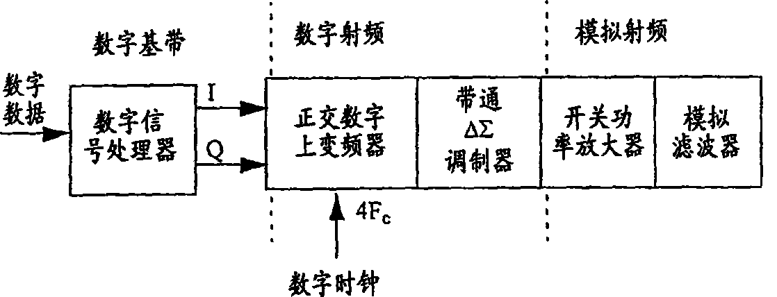
[0083] Example 1: Returning to the embodiment in Fig. 3, we select L 1 = 1 and L 2 =4. We also set the phase offset θ = 0 within the arguments of cos( ) and sin( ) driving the synchronous and quadrature modulators. data sample {i k} is the kth sample from the synchronous encoder 302a, similarly, the data sample {q k} is the kth sample from quadrature encoder 302b. Use a frequency of 4F c of clock pulses, which is higher than the carrier frequency F c 4 times higher, the samples from the encoder are effectively sampled and held 4 consecutive times by the interpolator 318 until the next kth sample arrives. Synchronous and quadrature modulator 320 is effectively an arithmetic multiplier. Each multiplier has two inputs and an output. The synchronous modulator 320a receives the synchronous samples from the interpolator 318a and also receives a periodic sequence {1, 0, -1, 0} which is the result of the trigonometric operation cos(2πn / 4), each carrier period with a carrier fr...
example 2
[0084] Example 2: Same as Example 1 above, we choose L 1 = 1 and L 2 =4. This time however we set the phase offset θ = π / 4 within the arguments of cos( ) and sin( ) driving the synchronous and quadrature modulators. Note that it is important to set the phase offset to θ=π / 4 in some cases. In particular, CDMA standards IS-95, IS-95a, IS-98 and IS-2000 require π / 4 offset quadrature phase shift keying as a modulation scheme. Those with common sense in the field of data modulation know that using π / 4 offset quadrature phase shift keying instead of zero offset is beneficial in reducing the peak-to-average ratio otherwise used as a crest factor. Returning to the operation mentioned above, the data sample {i k} is the kth sample from the synchronous encoder 302a, similarly, the data sample {q k} is the kth sample from quadrature encoder 302b. Using a clock pulse with a frequency of 4Fc, which is 4 times higher than the carrier frequency Fc, the samples from the encoder are effe...
example 3
[0087] Example 3: As in Example 2 above, L 1 = 1, L 2=4 and θ=π / 4. But in the noise reshaping coder 302 3D quantization is used. Therefore, there are nine possible data sequences per carrier cycle, and the layout diagram will include a matrix of nine symbol points according to the following I-Q coordinate system: (1,0), (1,1), (0, 1), (-1, 1), (-1, 0), (-1, -1), (0, -1), (1, -1), and (0, 0). According to the nine symbol points in the coordinate diagram, the nine possible series become: {1, -1, -1, 1}, {2, 0, -2, 0}, {1, 1, -1, - 1}, {0, 2, 0, -2}, {-1, 1, 1, -1}, {-2, 0, 2, 0}, {-1, -1, 1, 1}, { 0, -2, 0, 2}, {0, 0, 0, 0}.
PUM
 Abstract
Description
Claims
Application Information
 - R&D
- Intellectual Property
- Life Sciences
- Materials
- Tech Scout
- Unparalleled Data Quality
- Higher Quality Content
- 60% Fewer Hallucinations
Browse by: Latest US Patents, China's latest patents, Technical Efficacy Thesaurus, Application Domain, Technology Topic, Popular Technical Reports.
© 2025 PatSnap. All rights reserved.Legal|Privacy policy|Modern Slavery Act Transparency Statement|Sitemap|About US| Contact US: help@patsnap.com


