Linear sliding rail lubricating system

A lubricating system and linear slide rail technology, applied in the direction of engine lubrication, linear motion bearings, bearings, etc., can solve the problems of uneven service life, shortened service life, and inaccurate machining accuracy of the balls of the linear slide rail.

Active Publication Date: 2005-07-20
HIWIN TECH
View PDF0 Cites 13 Cited by
  • Summary
  • Abstract
  • Description
  • Claims
  • Application Information

AI Technical Summary

Problems solved by technology

The above two methods of lubricating oil flow on the same plane, and it is usually not easy to distribute the lubricating oil evenly to each ball return groove; just like a water pipe extracts a branch line from it, the amount of water cannot be evenly distributed. For each branch line, it is easy to cause uneven lubrication of the balls in different ball return grooves, resulting in uneven service life of the balls of the linear slide rail, shortening the overall service life
Moreover, since the lubricating oil path is exposed on the mating surface where the end cover and the slider are assembled, if there is an error in the machining accuracy or the surface roughness is not good, it is easy to cause the lubricating oil to overflow from this mating plane when the user adds lubricating oil

Method used


Image

  • Linear sliding rail lubricating system
  • Linear sliding rail lubricating system
  • Linear sliding rail lubricating system

Examples


Embodiment Construction

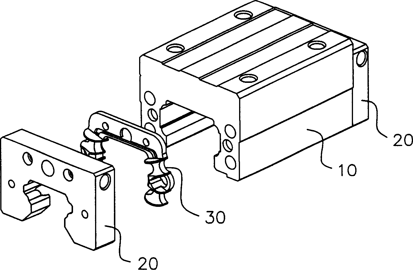
[0033] figure 1 It is a three-dimensional schematic diagram of the lubrication system of the linear slide rail of the present invention; wherein, end caps 20 and cover plates 30 are provided at both ends of the slider 10, and the end caps 20 and cover plates 30 can be combined into a complete reflux groove for the balls to turn and return.

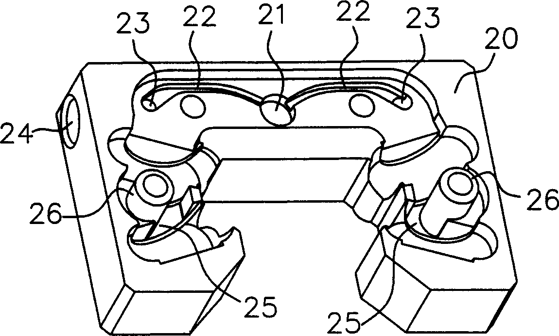
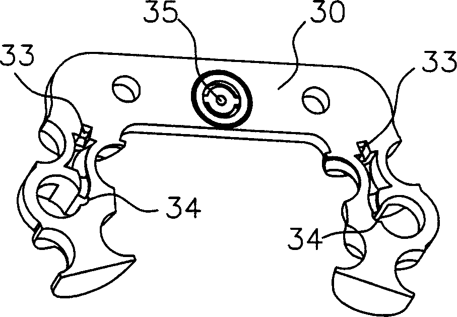
[0034] figure 2 for figure 1 The three-dimensional schematic diagram of the end cap; image 3 for figure 1 Front perspective schematic diagram of the cover plate; Figure 4 for figure 1 The perspective view of the reverse side of the cover plate; the end cover 20 has two oil injection directions: the oil injection hole 21 on the end surface and the oil injection hole 24 on the side. Part 35 has the effect of blocking the lubricating oil from flowing to the end surface of the slider. The lubricating oil is led to both sides from the guide oil passage 32, and then enters the oil holes 33 on both sides to transfer the lubricating oi...


PUM


Abstract

The invention is a structural design about a type of lubricative system of a linear slide-rail. It redesighs the oilway of lubricating oil--ameliorate planar oilway used to be known of linear slide-rail for tridimensional oilway,which makes lubricating oil circulate tridimensionally to interspace of counter-flow vat of above and below balls so that the lubricating oil can contribute to each counter-flow vat to lubricate balls. In addition, it sets up the lubricating location on the matching surface of end cap and cover board, but the slide block, in pairs or groups so that it can also prevent lubricating oil over falling from the matching surface of the end cap and the cover board to a certain degree to advance the leakproofness of oilway.

Description

technical field [0001] The invention relates to a lubricating system mechanism design of a linear slide rail, in particular to a redesign of the lubricating oil flow path, so that the lubricating oil of the linear slide rail can be evenly distributed to each return groove, and the sealing of the lubricating system is improved. sex. Background technique [0002] The general machine is equipped with a linear guide mechanism, the linear slide rail is a kind of linear guide mechanism, and the linear slide rail must have sufficient lubricating oil to lubricate the balls, so that it can operate normally without compromising the service life. [0003] The lubricating oil flow path of the linear slide, such as Figure 10 As shown, an oil nipple hole 61 is usually reserved on the end cover 60, and then a specific oil passage 62 is reserved on the overlapping surface of the end cover 60 to cooperate with the end surface of the slider to form a lubricating oil flow path. The lubricati...

Claims


Application Information

Patent Timeline
Patent Type & Authority Applications(China)
IPC IPC(8): F16C29/04F16N1/00F16N7/38
Inventor 林芸伊陈恩傑
Owner HIWIN TECH
Why Eureka
Try Eureka