Filter plate and high-pressure piston type solid-liquid separation device made of same

A solid-liquid separation, high-pressure piston technology, used in presses, manufacturing tools, dewatering/drying/concentrating sludge treatment, etc., can solve the problems of reducing sludge moisture content, unfavorable sludge dispersion, weak extrusion force, etc.

Pending Publication Date: 2018-11-23
厦门厦工重工有限公司
View PDF1 Cites 10 Cited by
  • Summary
  • Abstract
  • Description
  • Claims
  • Application Information

AI Technical Summary

Problems solved by technology

[0002] The industry discloses a piston filter, specifically referring to the patent publication number CN205073756 U, the piston filter is used to reduce the water content of sludge, and the piston filter includes a sleeve-shaped piston 1a, a sealing plate 2a, and a filter plate 3a And the discharge pipe 4a, the bottom of the sleeve-shaped piston 1a is provided with a sealing plate 2a, the bottom of the sealing plate 2a is provided with a filter plate 3a, and the upper surface and the lower surface of the filter plate 3a are horizontally provided with vertical and horizontal communication A network structure composed of linear grooves 31a, in which several through holes 32a leading to the upper and lower surfaces are provided, and the discharge pipe 4a is inserted between the sealing plate 2a and the filter plate 3a The movable end of an oil cylinder 5a is fixedly connected to the

Method used


Image

  • Filter plate and high-pressure piston type solid-liquid separation device made of same
  • Filter plate and high-pressure piston type solid-liquid separation device made of same
  • Filter plate and high-pressure piston type solid-liquid separation device made of same

Examples


Embodiment Construction

[0030] In the description of the present invention, "above" includes the original number, that is, "more than two" refers to two or more than two; the terms "first" and "second" are only used for descriptive purposes, and cannot be interpreted as indicating or implying Relative importance or implicit indication of the number of technical features indicated. Thus, a feature defined as "first" and "second" may explicitly or implicitly include one or more of these features. In the description of the present invention, "several" means two or more, unless otherwise specifically defined.

[0031] The present invention will be described in detail below in conjunction with the accompanying drawings and specific embodiments.

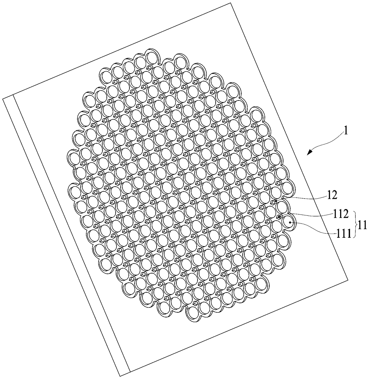
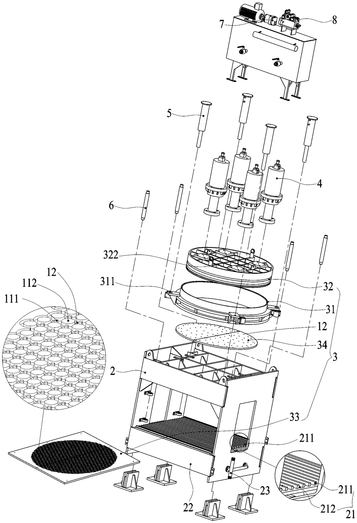
[0032] Such as image 3 , the present invention discloses a filter plate 1 for solid-liquid separation, on the surface of the filter plate 1 facing the object to be filtered, there are criss-cross convex grains 11, and between the convex grains 11 and the conve...


PUM


Abstract

The invention discloses a filter plate and high-pressure piston type solid-liquid separation device made of the same. Vertical and horizontal staggered projecting particles are arranged on the surfaceof the filter plate facing filtered objects, and water passing through holes penetrate the filter plate and are formed among the projecting particles. The high-pressure piston type solid-liquid separation device comprises a frame, a filter component, a piston oil cylinder, a lifting oil cylinder, a guide rod, an oil pump and a control system, the lifting oil cylinder drives a filter cylinder to vertically move along the guide rod, the piston oil cylinder drives a piston to vertically move along the filter cylinder, a first filter plate body and a second filter plate body are provided with thefilter plate, and the projecting particle surfaces of the first filter plate body and a second filter plate body are oppositely arranged. By the aid of the scheme, the extruding surface of the filterplate is provided with point-like distributed projecting particles, the contact areas among the filter plate and the filtered objects are greatly increased, more moisture can be extruded by the filter plate under the same extruding force, and solid-liquid separation effects are good.

Description

technical field [0001] The invention relates to an environmental protection machine, in particular to a device for efficiently dehydrating sludge, fungus residue, pomace and the like. Background technique [0002] The industry discloses a piston filter, specifically referring to the patent publication number CN205073756 U, the piston filter is used to reduce the water content of sludge, and the piston filter includes a sleeve-shaped piston 1a, a sealing plate 2a, and a filter plate 3a And the discharge pipe 4a, the bottom of the sleeve-shaped piston 1a is provided with a sealing plate 2a, the bottom of the sealing plate 2a is provided with a filter plate 3a, and the upper surface and the lower surface of the filter plate 3a are horizontally provided with vertical and horizontal communication A network structure composed of linear grooves 31a, in which several through holes 32a leading to the upper and lower surfaces are provided, and the discharge pipe 4a is inserted between...

Claims


Application Information

Patent Timeline
IPC IPC(8): B30B9/06B30B9/26C02F11/12
CPCC02F11/121B30B9/06B30B9/26
Inventor 邢奕廖清德白春荣曾悬荣林如阳苏占杰江长青郭丹辉
Owner 厦门厦工重工有限公司
Why Eureka
Try Eureka