Metre scattering polarization micro-pulse laser radar control method and device

A technology of laser radar and control method, applied in the field of optical environment monitoring and electronics, can solve the problems of limited application range of laser radar, high all-weather operation cost, low degree of system integration, etc., achieving light weight, simple structure, continuous operation moving effect

Active Publication Date: 2005-07-20
ANHUI INST OF OPTICS & FINE MECHANICS - CHINESE ACAD OF SCI
View PDF0 Cites 37 Cited by
  • Summary
  • Abstract
  • Description
  • Claims
  • Application Information

AI Technical Summary

Problems solved by technology

Therefore, the high cost, bulky and difficult to move of the system limit the application range of lidar
[0006] 2) The degree of system integration is low and it is difficult to run automatically
[0007] 3) High cost of all-weather operation
[0008] 4), pulsed laser eye safety issues for operators and ground personnel

Method used


Image

  • Metre scattering polarization micro-pulse laser radar control method and device
  • Metre scattering polarization micro-pulse laser radar control method and device
  • Metre scattering polarization micro-pulse laser radar control method and device

Examples


Embodiment Construction

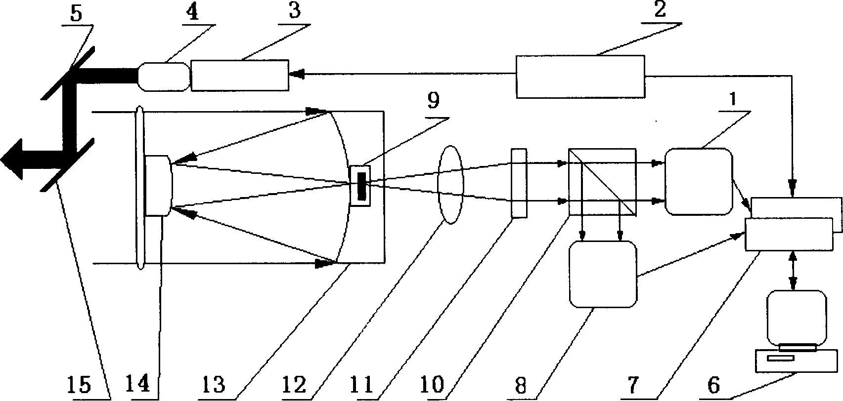
[0023] see Figure 1-4 .

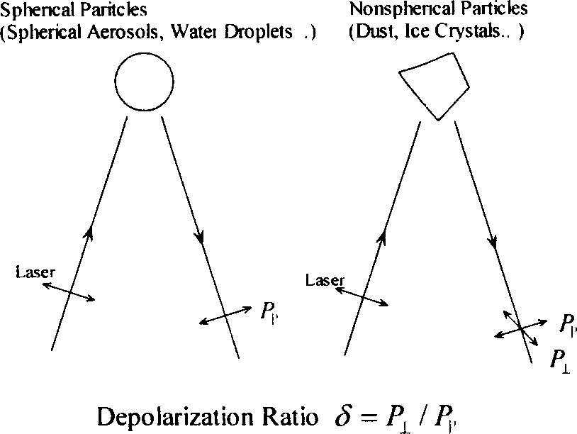
[0024] Meter scattering polarization micro-pulse laser radar method, the laser synchronous output pulse signal sent out by the small semiconductor pumped YAG frequency-doubled polarization laser (3) is transmitted to the photon counting card (7), which is used for counting and aligning the photon counting card Accumulation work; the polarized laser light emitted by the polarized laser (3) is input into the beam expander (4) for beam expansion, and then emitted to the sky after beam expansion, the laser is scattered by the aerosol in the atmosphere, and the spherical particles in the aerosol The backscattered light of non-spherical particles will not change the polarization direction of the laser, but the backscattered light of non-spherical particles will change the polarization direction of the laser to form a component (depolarization) perpendicular to the original laser polarization direction. The backscattered echo signals from the spherical and...


PUM

PropertyMeasurementUnit
pore sizeaaaaaaaaaa
reflectanceaaaaaaaaaa

Abstract

The invention discloses a dispersive polarized micropulse laser light radar control method and device, inputting polarized laser light emitted by a small-scale semiconductor pumping YAG frequency doubling polarizing laser as working into a beam expander for expanding, then sending the laser to the sky, where the laser is dispersed by aerosol in the atmosphere, the backward dispersed light of spherical particles in the aerosol will not change the polarizing direction of the laser light and that of nonspherical particles will change the polarizing direction of the laser light to form a component vertical to the polarizing direction of the original laser light (i.e. depolarized). The backward dispersive echo signals coming from the spherical and nonspherical particles are received by an optical telescope and two lights of different polarizing directions are separated by a light separating prism and sent to two detectors, respectively; a photon counter card makes contraposition counting and accumulation processing in the time sequence of photoelectric pulse signal returning from the space, and the processed result is stored into corresponding data memory cells; two signals collected are calculated by XJ-PMPL software to obtain echo depolarization degree, thus obtaining space distribution outline of nonspherical particles. Besides, it can also combine the two signals to obtain the total strength distribution of backward dispersed light, therefore the polarized micropulse laser light radar can also complete the functions of a general micropulse radar.

Description

technical field [0001] The invention relates to the fields of optical environment monitoring and electronics, in particular to a novel meter-scattering polarization micro-pulse laser radar and its control method and device. Background technique [0002] Meter scattering lidar is a high-tech means to quickly monitor the atmospheric environment in a wide range. It obtains the vertical profile of the atmospheric extinction coefficient by quantitatively analyzing the backscattering echoes generated by atmospheric aerosols (floating dust, particulate matter, smoke and dust) on the laser according to the physical effects of the atmosphere on laser scattering, absorption, and extinction. This achieves the purpose of atmospheric environment detection. [0003] Lidar is composed of laser emission, atmospheric backscatter echo receiving optical unit and data processing and control electronics system. If the atmosphere is relatively clean, due to the existence of atmospheric molecule...

Claims


Application Information

Patent Timeline
Patent Type & Authority Applications(China)
IPC IPC(8): G01N21/47G01N21/53G06F19/00
CPCY02A90/10
Inventor 纪玉峰徐赤东胡欢陵
Owner ANHUI INST OF OPTICS & FINE MECHANICS - CHINESE ACAD OF SCI
Why Eureka
Try Eureka