
Node structure for combined beam and concrete column and construction thereof

A technology of concrete columns and joint structures, applied to truss structures, columns, joists, etc., can solve the problems of lack of research on beam-column joints, and achieve the effects of increased strength, uniform internal force transmission, and uniform internal force distribution

Inactive Publication Date: 2005-07-27
SOUTH CHINA UNIV OF TECH
View PDF0 Cites 15 Cited by
  • Summary
  • Abstract
  • Description
  • Claims
  • Application Information

AI Technical Summary

Problems solved by technology

[0004] In the prior art, the research on the performance of composite beams and concrete columns is relatively extensive, but the research on beam-column joints in the structural system composed of composite beams and concrete columns is still very scarce.

Method used


Image

  • Node structure for combined beam and concrete column and construction thereof
  • Node structure for combined beam and concrete column and construction thereof

Examples


Embodiment Construction

[0024] The present invention will be further described in detail below in conjunction with the embodiments and the accompanying drawings, but the embodiments of the present invention are not limited thereto.

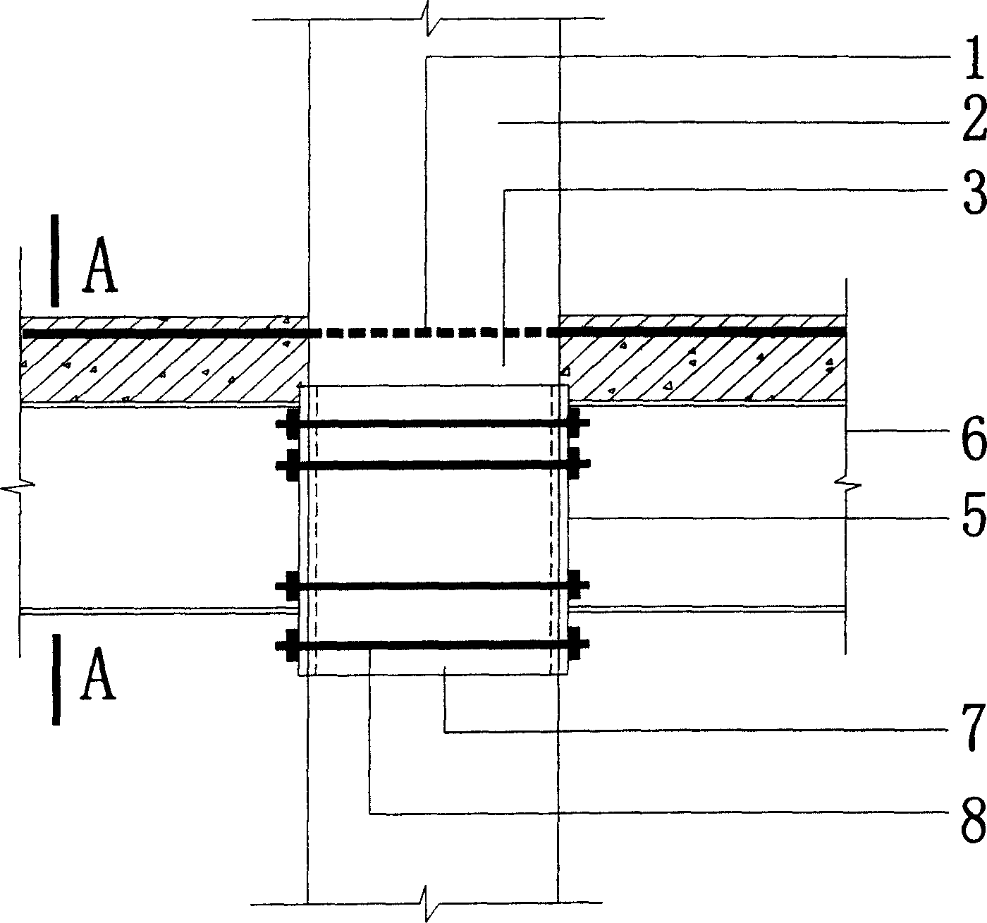
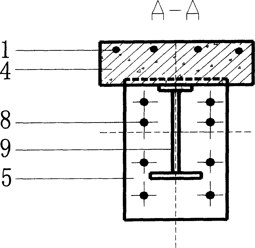
[0025] figure 1 The specific structure of the composite beam and concrete column joint structure is given, such as figure 1 As shown, the composite beam and concrete column joint structure includes the concrete 3 in the core area of ​​the joint, the steel plate hoop 7, the overhanging end plate 5, the long rod bolt 8, and the negative steel bar 1 of the composite beam 6. The concrete 3 in the core area of ​​the joint is a combination The concrete at the junction of the beam 6 and the concrete column 2, the steel plate hoop 7 is wrapped on the outer peripheral surface of the concrete 3 in the core area of ​​the node, the steel plate hoop 7 and the overhanging end plate 5 are located under the negative steel bar 1, and the two overhanging end plates 5 pass through The lon...


PUM

PropertyMeasurementUnit
Thicknessaaaaaaaaaa

Abstract

A node structure for combined beam and concrete column is composed of the concrete in the core region of node, steel-plate hoop, extended plate, long screw bolt, and the negative reinforcement of combined beam. Its construction method includes such steps as calculating the stress of node, and the number and diameter of long screw bolts, determining the sizes of extended plate and steel-plate hoop and making them, welding the extended plates with I-shaped beam, installing all members, pouring concrete, and turning the long screw bolts for closing the extended plate to steel-plate hoop.

Description

technical field [0001] The invention relates to the field of structural engineering in civil engineering, in particular to a joint structure of composite beams and concrete columns and a construction method thereof. Background technique [0002] Steel and concrete composite beams can give full play to the strengths of steel and concrete. Our country began to study the composite beam structure in the early 1950s, and then it has been widely used in highway and railway bridges. The use of composite beams in housing construction is more economical than the use of concrete beams. During the use of composite beams, the overall stability of the beams can be ignored, and the advantages of steel and concrete can be fully utilized. It can save materials, reduce the weight of the floor, and reduce the beam height. , Enhance rigidity and bearing capacity. [0003] Compared with the general concrete structure system, the structural system composed of reinforc...

Claims


Application Information

Patent Timeline
IPC IPC(8): E04B1/58E04C3/02E04C3/30
Inventor 马宏伟韩小雷陈兰
Owner SOUTH CHINA UNIV OF TECH
Learn More