Displacement controllable air spring vibrating insulative basement
An air spring and vibration isolation technology, applied in the direction of springs, gas shock absorbers, springs/shock absorbers, etc., can solve the problems of short service life, easy wear and tear, and the width of the non-sensing belt cannot be adjusted in real time as needed, so as to prolong the service life. longevity, wear-free effect
- Summary
- Abstract
- Description
- Claims
- Application Information
AI Technical Summary
Problems solved by technology
Method used
Image

Examples
Embodiment 1
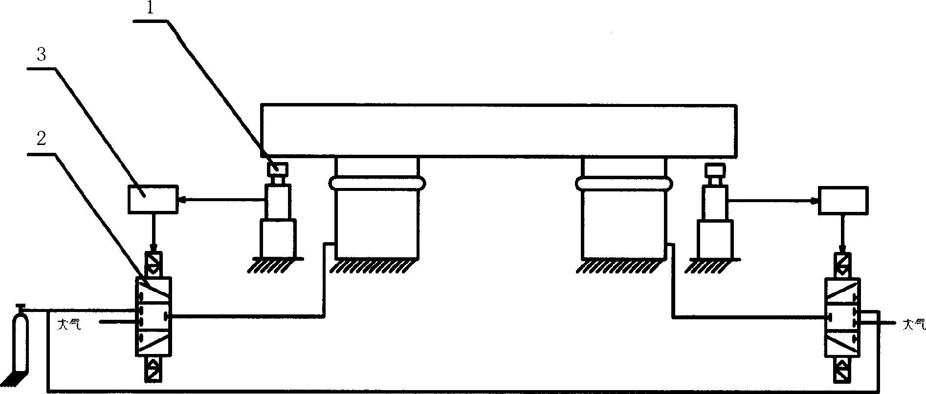
[0027] Such as figure 1 As shown, an air spring vibration isolation foundation, the height control unit is composed of a displacement sensor 1, a controller 3, and an electromagnetic reversing valve 2, and a non-contact displacement sensor 1 is used to measure the relative displacement between the ground and the base, and the displacement sensor 1 The output line of the controller 3 is connected to the input signal line of the controller 3, the output of the controller 3 is connected to the coil of the electromagnetic reversing valve 2, and the gas circuit interface of the electromagnetic reversing valve 2 is respectively connected to the ambient air, the air spring and the air supply system;
Embodiment 2
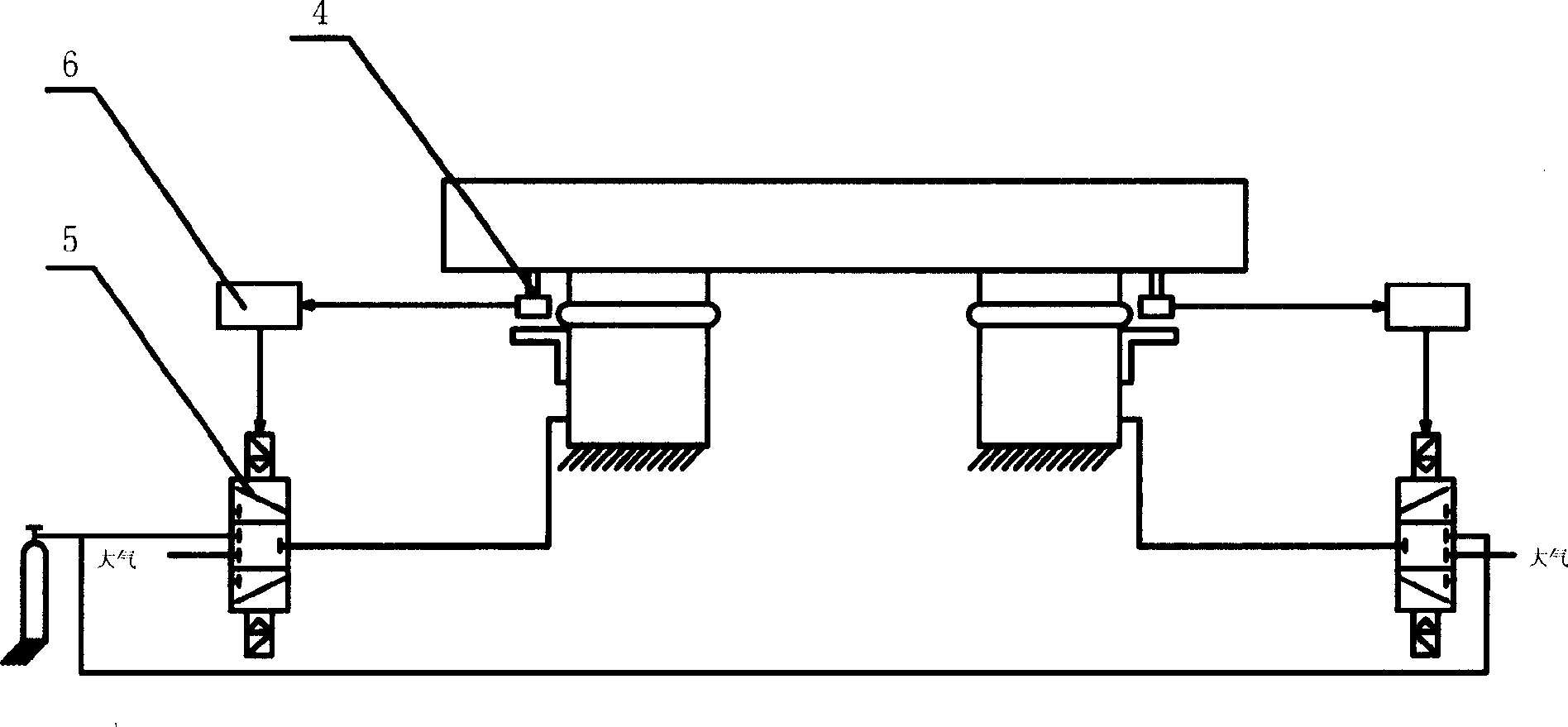
[0029] Such as figure 2 As shown, an air spring vibration isolation foundation, the height control unit is composed of a displacement sensor 4, a controller 6, and an electromagnetic reversing valve 5, and a non-contact displacement sensor 4 is used to measure the relative displacement between the ground and the base, and the displacement sensor 4 The output line of the controller 6 is connected to the input signal line of the controller 6, the output of the controller 6 is connected to the coil of the electromagnetic reversing valve 5, and the gas circuit interface of the electromagnetic reversing valve 5 is connected to the ambient air, the air spring and the air supply system respectively;
Embodiment 3
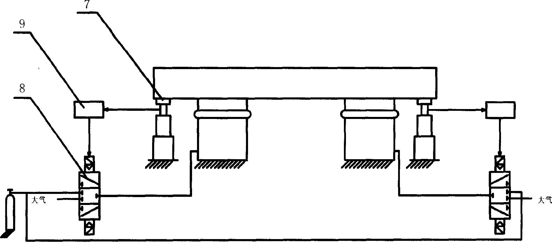
[0031] Such as image 3 As shown, an air spring vibration isolation foundation, the height control unit is composed of a displacement sensor 7, a controller 9, and an electromagnetic reversing valve 8, and the contact displacement sensor 7 is used to measure the relative displacement between the ground and the base body. The output line is connected to the input signal line of the controller 9, the output of the controller 9 is connected to the coil of the electromagnetic reversing valve 8, and the air circuit interface of the electromagnetic reversing valve 8 is respectively connected to the ambient air, the air spring and the air supply system;
PUM
 Abstract
Description
Claims
Application Information
 - Generate Ideas
- Intellectual Property
- Life Sciences
- Materials
- Tech Scout
- Unparalleled Data Quality
- Higher Quality Content
- 60% Fewer Hallucinations
Browse by: Latest US Patents, China's latest patents, Technical Efficacy Thesaurus, Application Domain, Technology Topic, Popular Technical Reports.
© 2025 PatSnap. All rights reserved.Legal|Privacy policy|Modern Slavery Act Transparency Statement|Sitemap|About US| Contact US: help@patsnap.com