
Automatic thermostatic heater

A constant temperature heating and automatic technology, applied in induction heating devices, induction heating, measuring devices, etc., can solve the problems of easy overheating and uneven heating, and achieve the effects of energy saving, convenient operation, and easy temperature control.

Inactive Publication Date: 2005-07-27
SICHUAN UNIV
View PDF0 Cites 6 Cited by
  • Summary
  • Abstract
  • Description
  • Claims
  • Application Information

AI Technical Summary

Problems solved by technology

This kind of heating device does not heat evenly, and is easy to overheat, resulting in the generation of bubbles in the fluid flowing through the heating reaction coil, which interferes with the analysis and detection.

Method used


Image

  • Automatic thermostatic heater
  • Automatic thermostatic heater
  • Automatic thermostatic heater

Examples


Embodiment 1

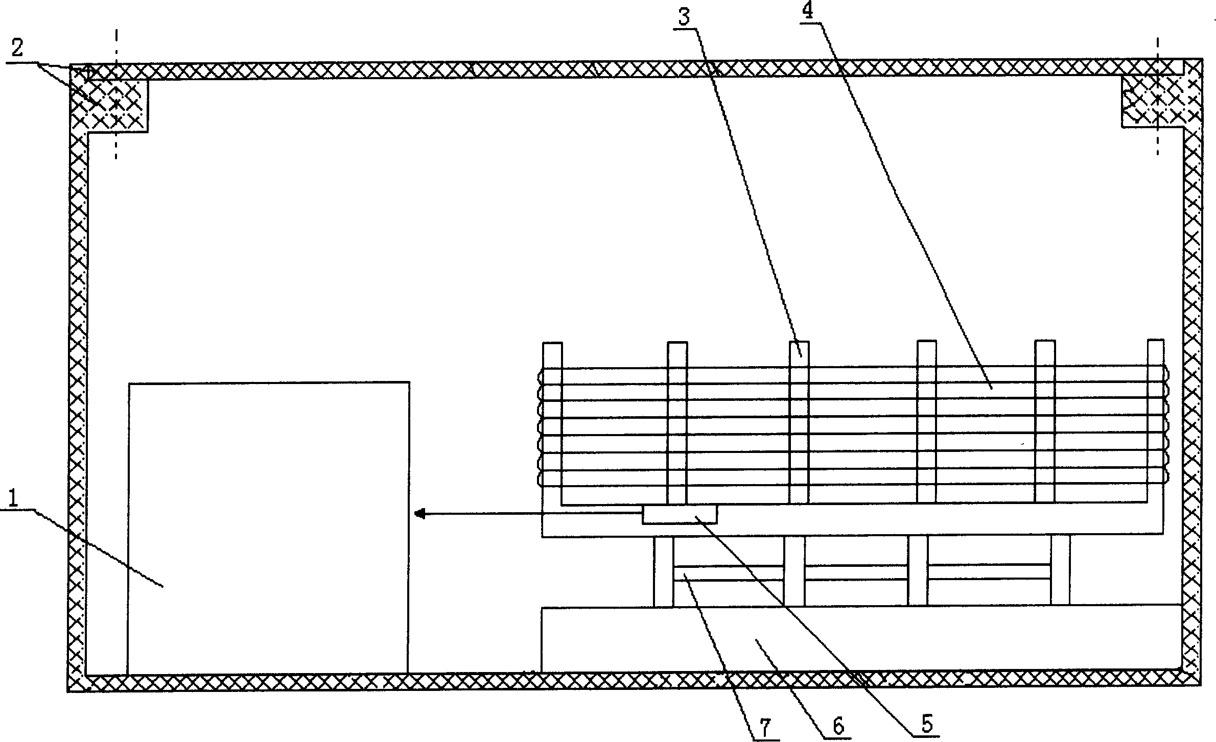
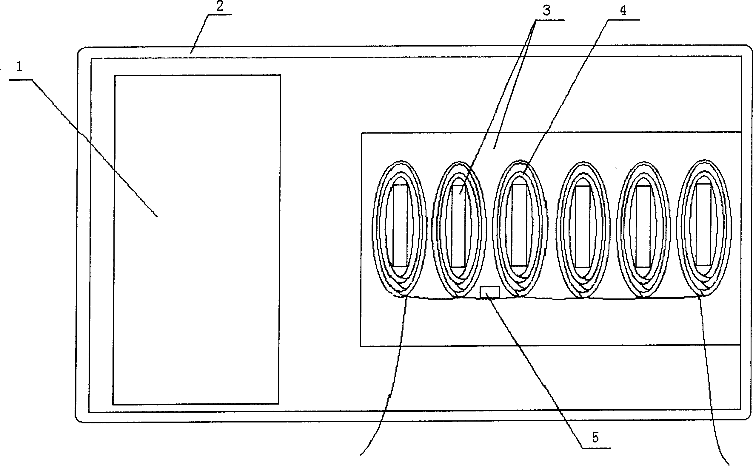
[0025] The structure of the automatic constant temperature heating device in the present embodiment is as follows: figure 1 , figure 2 As shown, it includes a casing 2 , a heater located in the casing, a heat transfer body 3 , a heating reaction coil 4 , a temperature control and temperature measuring instrument 1 and a temperature sensor 5 . The heat transfer body 3 is composed of a rectangular plate and a heat transfer sheet perpendicular to the rectangular plate. The material is cast aluminum, and there are six heat transfer sheets; Out of the shell 2. The heater is composed of an insulating base 6, a ceramic heating element 7 installed on the base, and a wire assembly connecting the ceramic heating element and a power supply, and the rectangular plate of the heat transfer body 3 is installed on the heater. Both the temperature sensor 5 and the temperature control and temperature measurement instrument 1 are commercially available. The temperature sensor 5 is installed i...

Embodiment 2

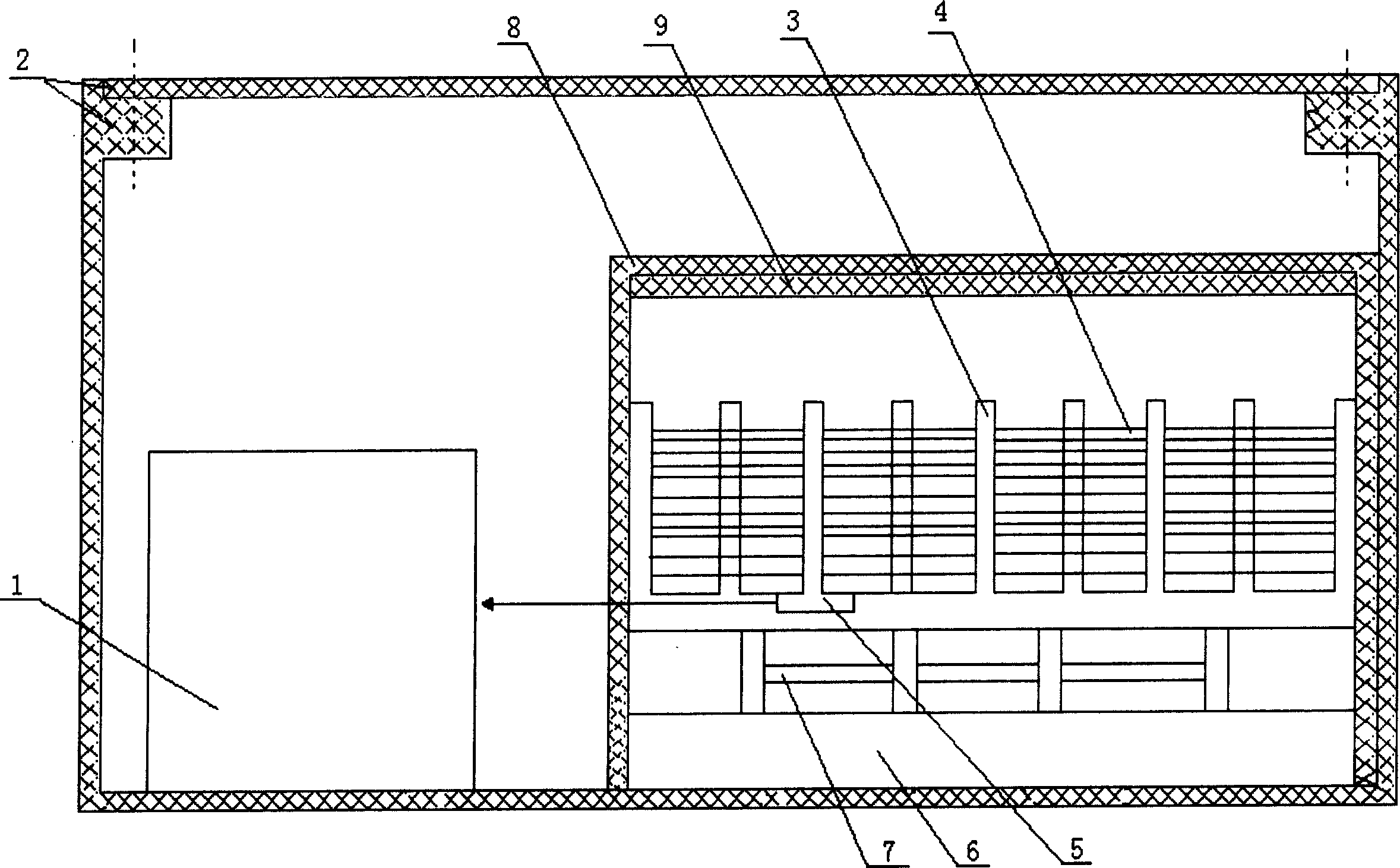
[0027] The structure of the automatic constant temperature heating device in the present embodiment is as follows: image 3 , Figure 4 shown. The difference from Example 1 is: 1. The heat transfer body 3 has nine heat transfer sheets, and the heating reaction coil 4 is wound on the heat transfer sheet at intervals, and the heat transfer sheet wrapped with the heating reaction coil is located between two sheets that are not wound with a heating coil. between the heating pads of the reaction coil. 2. The insulation cover 8 made of asbestos cardboard is installed, and the insulation cover 8 is set on the heat transfer body and the heater. Its shape and size match the shape and size of the combination of the heat transfer body and the heater; the inner wall of the top of the insulation cover Covered with a thermal insulation layer 9 made of polymer foam material.


PUM


Abstract

The invention consists of body case, heater in body case, heat transfer body, thermal reaction coil, temperature control and test meter,and temperature sensor. The heat transfer body is mounted on the heater. The thermal reaction coil is around the heat transfer body, and its liquor feeding end and liquor outputting end are threaded out body case. The temperature sensor is located in the temperature field formed by heat transfer body, and its output end is connected with input end of temperature control and test meter. The output end of temperature control and test is connected with the power of electric heater to control onoff of the power. A lagging can be sleeved on heat transfer body and heater.

Description

technical field [0001] The invention belongs to a heating device for flow injection analysis, ion chromatographic analysis and high performance liquid chromatographic analysis, in particular to an automatic constant temperature heating device. Background technique [0002] Flow injection analysis, ion chromatography analysis and high performance liquid chromatography analysis require heating and constant temperature when analyzing certain substances. In this case, the fluid flows through the heating reaction coil and reacts at a certain temperature is an important condition to ensure the accuracy of the test. . [0003] The heating of the heating reaction coil generally adopts oil bath or water bath heating device and cylinder heating device. The oil bath or water bath heating device is mainly composed of a heating agitator and a container filled with oil or water. When in use, the heating reaction coil is placed in a container filled with a certain amount of oil or water, ...

Claims


Application Information

Patent Timeline
Patent Type & Authority Applications(China)
IPC IPC(8): B01L7/00G01N30/00H05B6/06H05B6/10
Inventor 张新申蒋小萍
Owner SICHUAN UNIV
Learn More