Lime calcining rotary furnace

A converter and lime technology, applied in the field of calcined lime rotary furnace, can solve the problems of low efficiency, poor firing quality, pollution, etc., and achieve the effect of uniform heating and improved utilization rate

Inactive Publication Date: 2005-08-03
黄官禹
View PDF0 Cites 7 Cited by
  • Summary
  • Abstract
  • Description
  • Claims
  • Application Information

AI Technical Summary

Problems solved by technology

[0002] The existing lime firing kiln is a fixed kiln, the pollution is serious during the firing process, the firing quality is poor, the efficiency is low, the energy waste is serious, and the manufacturing cost is greatly increased.

Method used


Image

  • Lime calcining rotary furnace
  • Lime calcining rotary furnace

Examples


Embodiment Construction

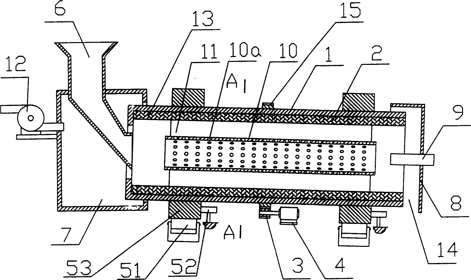
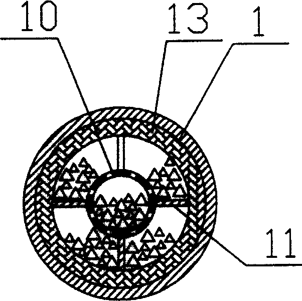
[0008] Such as figure 1 , figure 2 As shown, a lime calcining rotary furnace includes a cylindrical furnace body 1 installed in an inclined shape with a high front and a low rear. This installation method can ensure that the furnace material flows to the cylindrical furnace by its own gravity during the rotation of the furnace body 1. The discharge port at the lower end of the body 1; the inner wall of the cylindrical furnace body 1 is provided with a refractory layer 13, and the high end of the cylindrical furnace body 1 is provided with a feed hopper 6, and the lower end of the cylindrical furnace body 1 is located One end of the cylinder is provided with a discharge port 14, and a pulverized coal combustion injector 9 is installed at the lower end of the cylindrical furnace body 1. The outer side of the cylindrical furnace body 1 is provided with a driving device for driving the furnace body to rotate and The supporting wheel device supporting the furnace body is located ...


PUM


Abstract

The lime calcining rotary furnace has one cylindrical furnace body, one calcining sieve barrel set concentrically inside the cylindrical furnace body, and several partition boards set homogeneously between the calcining sieve barrel and the cylindrical furnace body. During the rotation of the furnace body, crushed limestone is distributed in the channels the calcining sieve barrel and the partition boards form, heated homogeneously with the flame of the coal powder burning sprayer, and made to shift toward the relatively lower discharge port. The present invention has raised heat energy utilization and continuous operation and is superior to fixed kiln.

Description

technical field [0001] The invention relates to a rotary kiln, in particular to a rotary kiln for calcining lime. Background technique [0002] The existing lime firing kiln is a fixed kiln, which causes serious pollution in the firing process, poor firing quality, low efficiency, serious energy waste, and greatly increases the manufacturing cost. Contents of the invention [0003] The technical problem to be solved by the present invention is to provide a lime calcining rotary kiln with high working efficiency, energy saving and light pollution. [0004] In order to achieve the above object, the technical solution of the present invention is: a lime calcining rotary furnace includes a cylindrical furnace body installed in an inclined shape with a high front and a low rear, a refractory layer is arranged on the inner wall of the cylindrical furnace body, The high end of the cylindrical furnace body is provided with a feed hopper, the low end of the cylindrical furnace bod...

Claims


Application Information

Patent Timeline
Patent Type & Authority Applications(China)
IPC IPC(8): C04B2/10C04B2/12
CPCY02P40/40
Inventor 黄官禹
Owner 黄官禹
Why Eureka
Try Eureka