Method for coorperating distributor and mixer of gas soot blower

A technology of a distribution device and a mixing device, which is applied to the heat exchange surface of boiler combustion to implement soot blowing, in the field of boilers, can solve the problems of inability to isolate the gas transfer area and the gas control area, the inability to separate air and gas, and the large volume of the mixing igniter. , to achieve the effect of stable and reliable operation method, good soot blowing effect and improving mixing efficiency

Inactive Publication Date: 2005-08-24
北京嘉德兴业科技有限公司
View PDF6 Cites 3 Cited by
  • Summary
  • Abstract
  • Description
  • Claims
  • Application Information

AI Technical Summary

Problems solved by technology

At present, a total mixed igniter, or a total separate mixing chamber, a total separate ignition chamber, and then a total generator are used, and the total pulsed crackling gas mixture is distributed and sent through multiple pipelines. To multiple heat exchange surfaces that need soot blowing; the disadvantages and disadvantages of this method are: the volume of a total mixing igniter is too large, the gas consumption is large, the mixing efficiency is low, the blowing from mixing ignition to the heat exchange surface During the whole process of ash, the air and gas cannot be separated, the gas transmission area and the gas control area cannot be separated, the reverse impact force is large, it is easy to cause tempering, the operation is unstable and unsafe, the electrical components and other components are easily damaged, and the structure is not good. Reasonable and unscientific methods

Method used


Image

  • Method for coorperating distributor and mixer of gas soot blower
  • Method for coorperating distributor and mixer of gas soot blower
  • Method for coorperating distributor and mixer of gas soot blower

Examples


Embodiment Construction

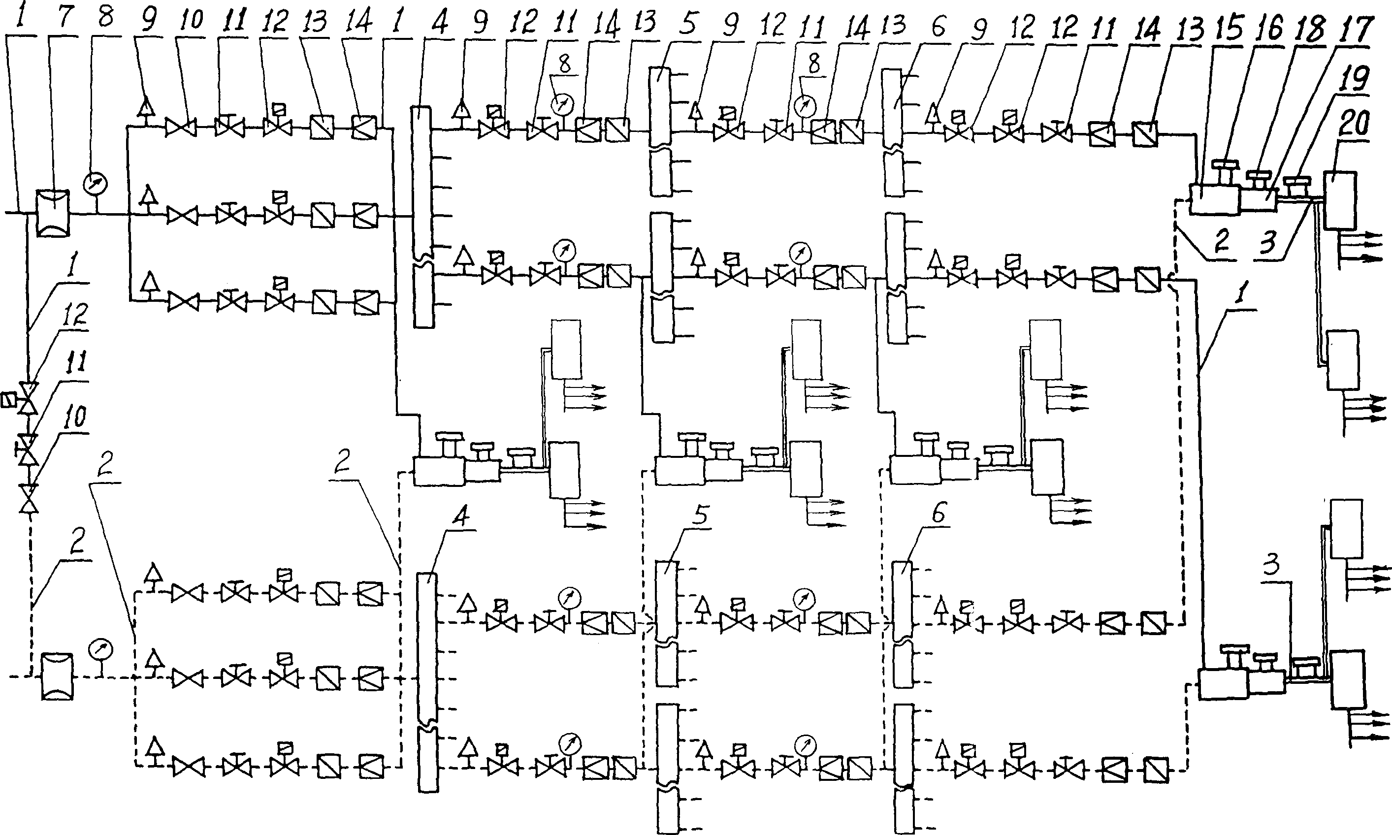
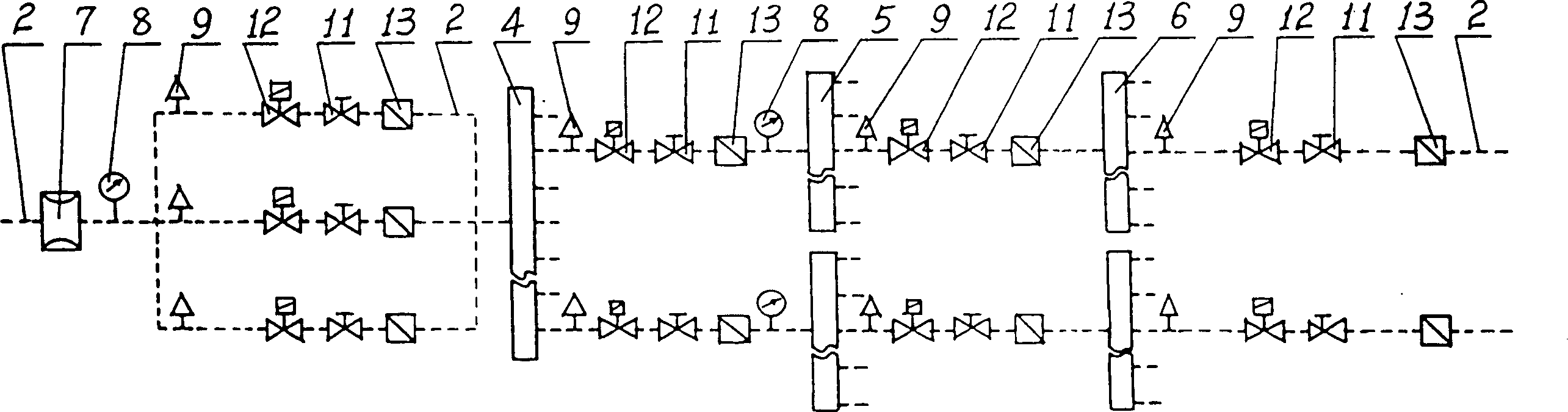
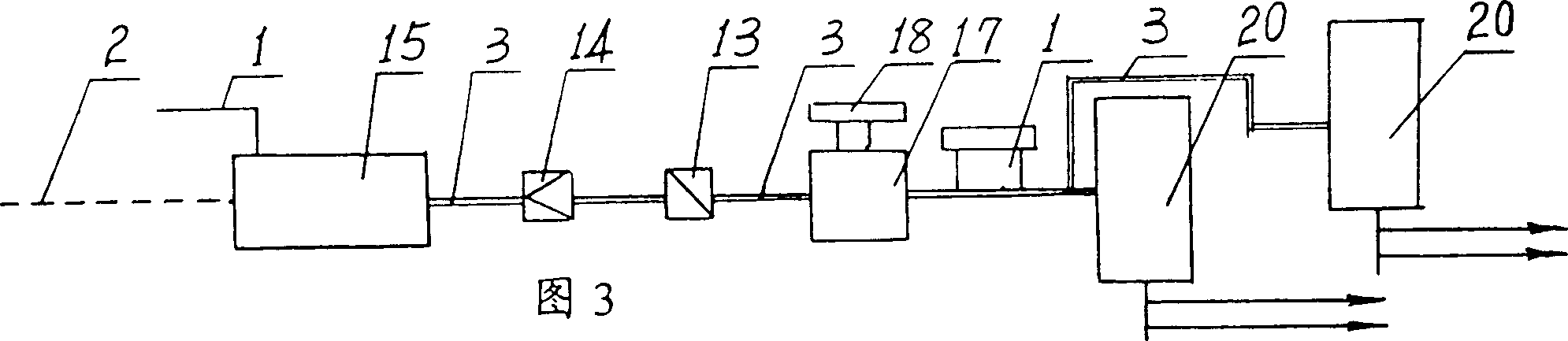
[0058] The present invention will be described in detail below in conjunction with the accompanying drawings. As attached to the manual figure 1 , 2 , 3 shows: a method for coordinating the distribution device and the mixing device of a gas soot blower, including a gas pipe 1, an air pipe 2, a fuel mixing pipe 3, a primary distribution device 4, a secondary distribution device 5, and a tertiary Distribution device 6, flow meter 7, pressure sensor 8, pressure stabilizing valve 9, main valve 10, regulating valve 11, pulse valve 12, check valve 13, flame arrester 14, mixing chamber 15, temperature sensor 16, ignition chamber 17, Igniter 18, state detector 19, generator 20, and a mixing igniter composed of mixing chamber 15, ignition chamber 17, and igniter 18;

[0059] The gas pipe 1 is sequentially connected with the pulse valve 12, the regulating valve 11, and the main valve 10, and connected with the air pipe 2 to form a gas passage replacement device for mutual replacement ...


PUM


Abstract

The invention relates to a method which admeasure device of the gas blower adapts with complex device. It includes: air channel interchange device consists of gas, air pipe and impulse, adjusting and main valve; gas or air conducting device consists of flowmeter, pressure sensor, pressure regulating valve, impulse valve, adjusting valve, main valve, backflow valve and fire retardant or air pipe; tertiary gas or air conducting device consists of primary and secondary gas or air channel conducting device consist of pressure regulating, impulse, adjusting valve and fire retardant and pressure sensor and gas or air pipe; pressure regulating, double impulse, adjusting and fire retardant device, backflow valve all connected by gas or air pipe. Gas and air channel conducting device connects with blending cavity and primary admeasuring device, so does the primary gas and air channel conducting device the mixing cavity and secondary admeasuring device, secondary gas or air channel conducting device the mixing cavity and tertiary admeasuring device. The tertiary gas and air conducting device connects with mixing cavity linked with temperature sensor, igniting cavity linked with igniter, combusting blending pipe, status monitor, and initiator. The furnace is for blowing the ashes.

Description

Technical field: [0001] The method for coordinating the distribution device and the mixing device of the gas soot blower of the present invention relates to the technical field of boilers; in particular, it relates to the technical field of soot blowing on the combustion heat exchange surface of the boiler; in particular, it relates to the distribution device and the mixing device of the gas soot blower matching method [0002] technology field. Background technique: [0003] During the combustion process of a boiler fueled by gas or oil, a dust layer will inevitably form on the heat exchange surface of the boiler, and the dust layer will form hard scaling under the action of high temperature, thereby affecting the normal combustion of the boiler. In order to solve this problem, the dust on the heat exchange surface of the boiler is usually blown off by a pulse burst method generated by a mixed igniter or a separate mixing chamber or a separate ignition chamber. The mixing...

Claims


Application Information

Patent Timeline
Patent Type & Authority Applications(China)
IPC IPC(8): F23D14/02F23D14/46F23J3/02
Inventor 张自强
Owner 北京嘉德兴业科技有限公司
Why Eureka
Try Eureka