Optical disk recording/playback apparatus and optical disk evaluation method
一种再生装置、光盘记录的技术,应用在记录/再现/删除方法、盘状记录载体、数字记录/再现等方向,能够解决不能正确进行跳动评价等问题,达到消除遗漏、正确评价跳动的效果
- Summary
- Abstract
- Description
- Claims
- Application Information
AI Technical Summary
Problems solved by technology
Method used
Image
Examples
no. 1 approach =
[0042] ===First Embodiment===
[0043]
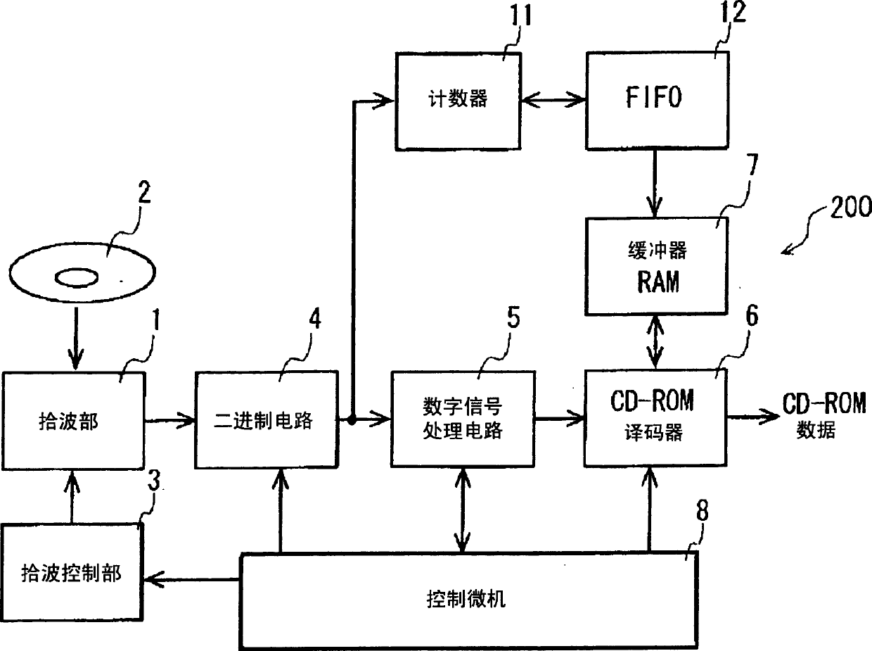
[0044] A CD recording and reproducing device 200 as an optical disc recording and / or reproducing device (hereinafter referred to as an optical disc recording and reproducing device) according to the first embodiment of the present invention has the configuration shown in FIG. 1 . In this embodiment, circuits that realize the same functions as those in the prior art shown in FIG. 20 are denoted by the same reference numerals, and their descriptions are omitted.
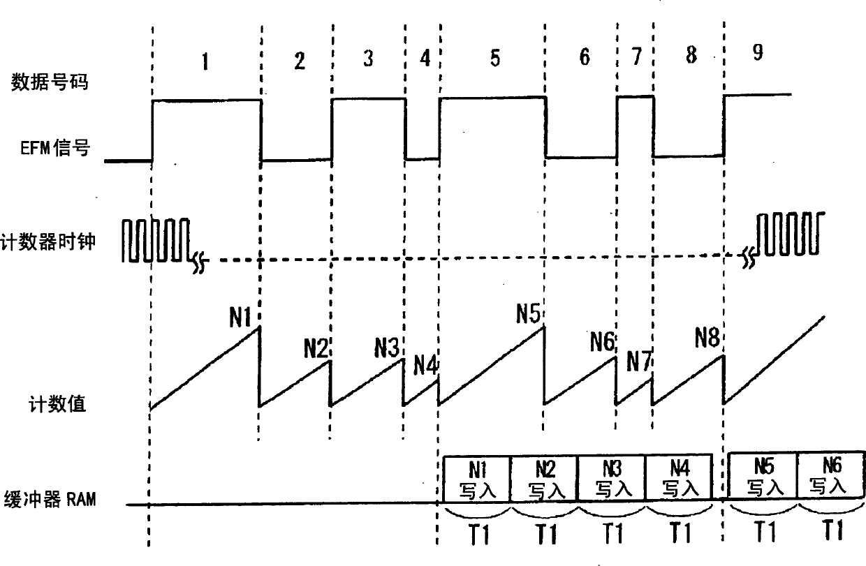
[0045] In the CD recording / reproducing apparatus 200 , the counter 11 is connected to the binary circuit 4 to acquire the EFM signal output from the binary circuit 4 . In addition, the counter 11 counts each clock period of the EFM signal with a counter clock having a higher frequency than the input EFM signal, and transfers the count value to the FIFO 12 which is a temporary storage circuit for temporarily storing each count value. The FIFO 12 is composed of registers and th...
no. 2 approach =
[0075] === Second Embodiment ===
[0076]
[0077] Groove wobble and LPP as a preformat method of DVD-R / RW media will be described with reference to FIG. 10 .
[0078] The DVD-R / RW medium is set with: groove tracks (recording grooves) formed in a spiral shape as tracks for recording data; and land tracks in which LPPs are formed in advance between adjacent groove tracks. In addition, the groove track is pre-zigged with a certain period. The zigzag frequency (wobble frequency) is about 140.6 KHz at the standard speed of DVD-R / RW. By multiplying the wobble frequency by 186 times, a clock signal corresponding to the mark unit length can be obtained. That is, when the DVD-R / RW standard speed "1 / 26.16 MHz" is represented by "1T", the period of one wobble frequency component is "186T".
[0079] The data recorded in the groove track has a plurality of ECC (Error Correcting Code) blocks as an error correction unit. One ECC block is composed of 16 sectors (sector 0 to sector 15), ...
example
[0118] In this way, according to the second embodiment of the present invention, due to the address information obtained from the pre-format information of the optical disc, each clock period of the EFM / EFMPlus signal corresponding to the desired partition area on the optical disc can be specified for jitter evaluation. , therefore, the reliability of the jitter evaluation can be improved. Also, according to the second embodiment of the present invention, the clock period specification for jitter evaluation and the counting operation of the counter 312 can be synchronized based on the address information and synchronization code acquired from the preformat information of the optical disc. In addition, this synchronization process is performed independently of the control microcomputer 308 which performs asynchronous control (push / inquiry) on the LPP / ADIP decoder 305, the counter control circuit 314, and the like. That is, according to the second embodiment of the present inven...
PUM
 Abstract
Description
Claims
Application Information
 - R&D
- Intellectual Property
- Life Sciences
- Materials
- Tech Scout
- Unparalleled Data Quality
- Higher Quality Content
- 60% Fewer Hallucinations
Browse by: Latest US Patents, China's latest patents, Technical Efficacy Thesaurus, Application Domain, Technology Topic, Popular Technical Reports.
© 2025 PatSnap. All rights reserved.Legal|Privacy policy|Modern Slavery Act Transparency Statement|Sitemap|About US| Contact US: help@patsnap.com


