Time-delay operation leakage circuit breaker

A technology of leakage protection switch and delay action, which is applied in the direction of protection switch, automatic disconnection emergency protection device, emergency protection device, etc., which can solve the problems of power failure, inability to grade protection, inability to delay tripping, etc., and achieve low cost increase , Simple structure, easy to process and manufacture

Inactive Publication Date: 2005-09-14
刘顺民
View PDF0 Cites 11 Cited by
  • Summary
  • Abstract
  • Description
  • Claims
  • Application Information

AI Technical Summary

Problems solved by technology

[0002] The leakage protection switch currently used cannot delay tripping regardless of the current, so it cannot be protected in different levels. Once leakage occurs, the multi-level leakage

Method used


Image

  • Time-delay operation leakage circuit breaker
  • Time-delay operation leakage circuit breaker

Examples


Embodiment Construction

[0013] The present invention will be described in further detail below in conjunction with the accompanying drawings.

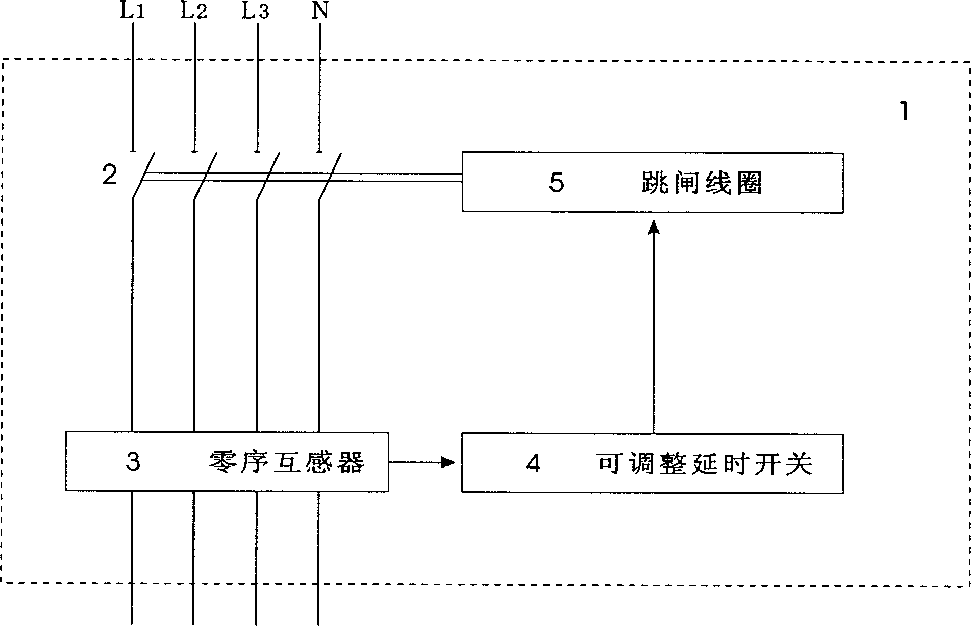
[0014] figure 1 It is a structural block diagram, three-phase four-wire through the switch contact (2) of the delay action leakage protection switch (1), the zero-sequence sensor (3) detects the leakage current, and the adjustable delay switch (4) can be started. Adjust the delay switch (4) to reach the set time, start the trip coil (5), and the switch contact (2) trips and trips.

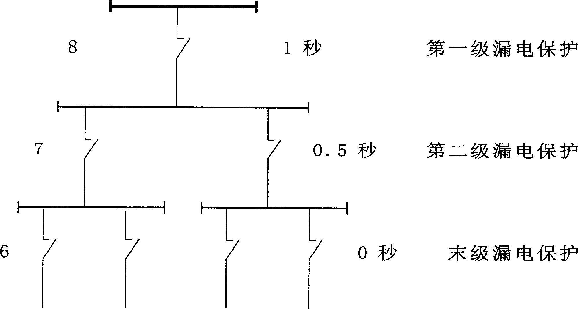
[0015] figure 2 It is an example hierarchical protection principle diagram of the present invention

[0016] Assuming that the time-delay action leakage protection switch (1) is composed of hierarchical protection, the protection time of the last level protection (6) is set to 0 seconds, the second level leakage protection (7) is set to 0.5 seconds, and the first level leakage protection (8) is set to For 1 second, the principle is that it cannot cause (6) (7) (8) three-level ...


PUM


Abstract

A time delay action leakage protection switch relates to a low voltage leakage protection switch suitable for low voltage circuit below 500v characterizing in realizing stage protection composed of a switch contactor, a zero sequence mutual inductor, an adjustable time delay switch and a breaking coil, among which, the leakage current can be detected and the adjustable time delay switch is started by the zero-sequence mutual inductor, the switch can be adjusted from zero, the time limit can be adjusted at zero state and breaks quickly if it works independently or used at the final stage.

Description

Technical field: [0001] The invention relates to the field of low-voltage leakage protection switches, and is suitable for low-voltage circuits below 500V. Background technique: [0002] The leakage protection switch currently used cannot delay tripping regardless of the current, so it cannot be protected in different levels. Once leakage occurs, the multi-level leakage switch trips at the same time, causing a large-scale power outage, especially for elevators, tower cranes, underground ventilation and lighting, etc. equipment, accidents may occur due to power outages. Invention content: [0003] The purpose of the present invention is to overcome the deficiencies of the prior art and provide a leakage protection switch with simple structure, low cost and adjustable delay action. Unnecessary outages caused by the range. [0004] The purpose of the present invention is to be achieved through the following technical solutions: [0005] The delay action leakage protection ...

Claims


Application Information

Patent Timeline
IPC IPC(8): H01H83/00H02H3/14
Inventor 刘顺民
Owner 刘顺民
Why Eureka
Try Eureka