Scanning probe microscope

A technology of scanning probe and microscope, which is applied in the field of scanning probe microscope, can solve the problems of short time, local probe technology tracking, etc.

Inactive Publication Date: 2005-09-21
INFINITESIMA
View PDF1 Cites 31 Cited by
  • Summary
  • Abstract
  • Description
  • Claims
  • Application Information

AI Technical Summary

Problems solved by technology

Moreover, many scientific, industrial, and physiological processes occur too briefly to be tracked using current local probe technology

Method used


Image

  • Scanning probe microscope
  • Scanning probe microscope
  • Scanning probe microscope

Examples


Embodiment Construction

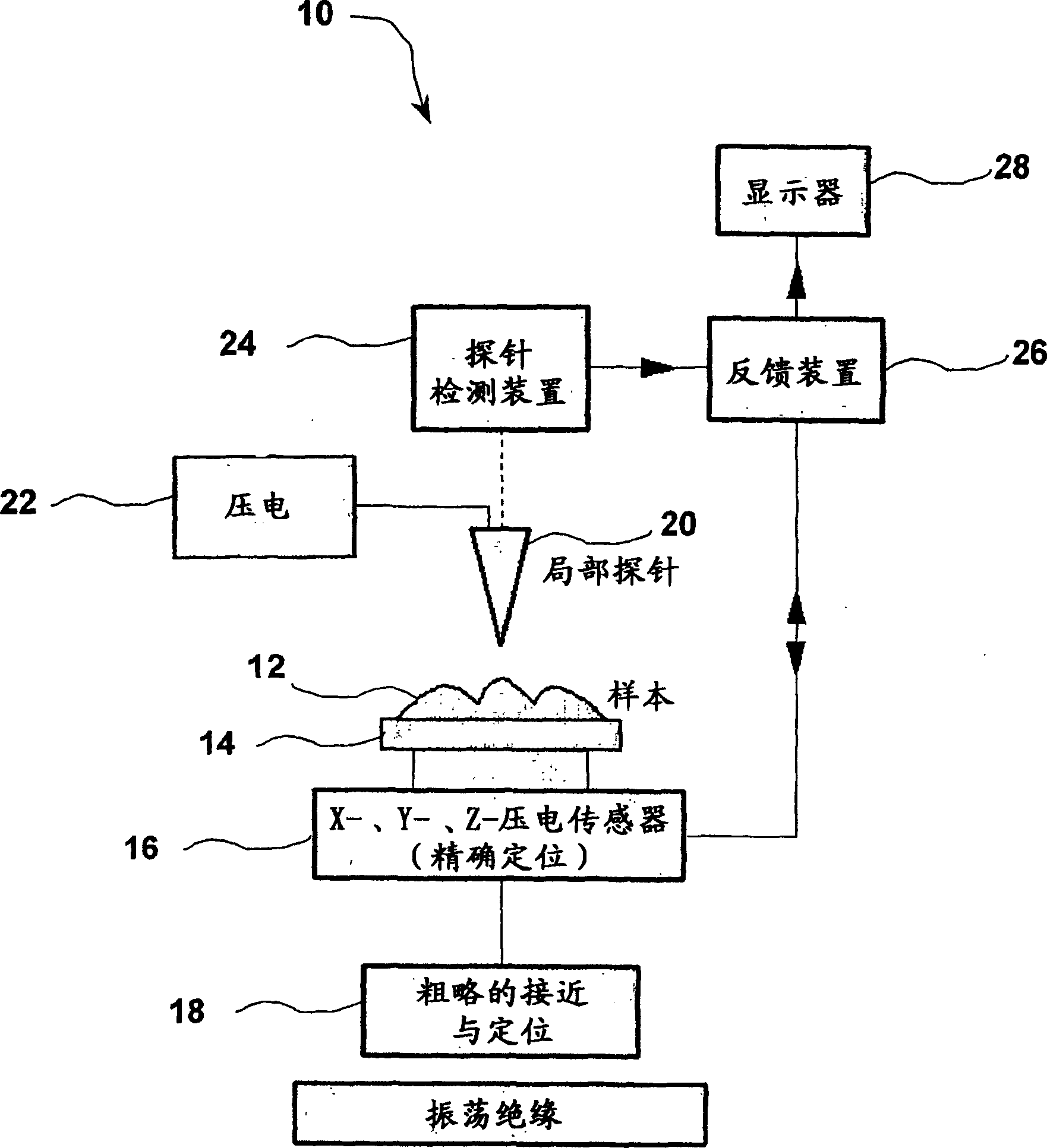
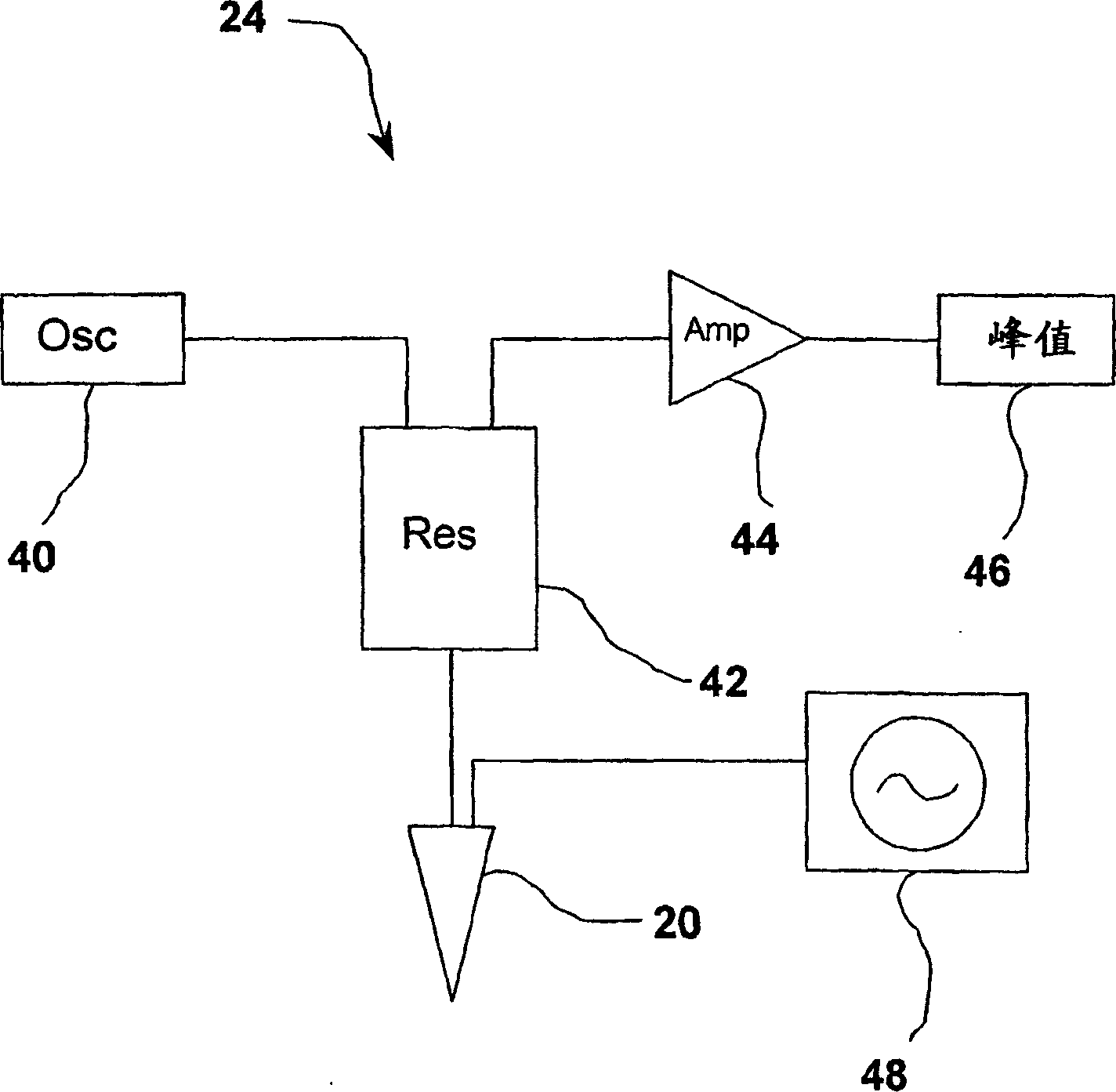
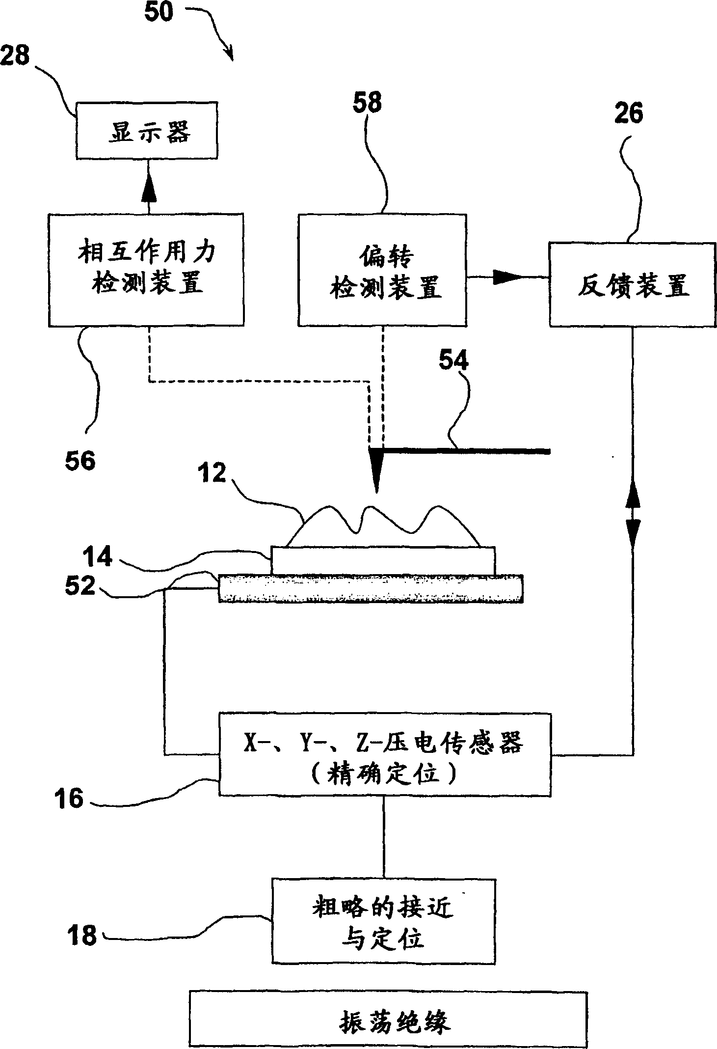
[0029] figure 1 An embodiment of a scanning capacitance microscope (SCM) of the present invention is shown. In Rev. Sci. Inst. 72 (6) "Zeptofarad" for Scanning Capacitance Microscopy (10 -21 ) Resolution Capacitive Sensors" describes existing SCM techniques and proves to be particularly useful when measuring 2D carrier profiles of semiconductor devices. As in the microscope described by Tran et al., figure 1The illustrated device 10 includes a ground plane 14 adapted to receive a sample 12 connected to a piezoelectric transducer 16 and a rough drive 18 . The metal probe 20 is connected to a second piezo drive 22 for driving the probe 20 at or near resonance, unlike any existing SCM technology drive. The first 16 or second 22 piezoelectric transducer drives the relative vertical motion of the probe 20 and sample 12 . In this embodiment it is a piezoelectric sensor 16 attached to the sample 12 . The device comprises a probe detection device 24, the detailed configuration o...


PUM


Abstract

A scanning probe microscope detects or induces changes in a probe-sample interaction. In imaging mode, the probe 54 is brought into a contact distance of the sample 12 and the strength of the interaction measured as the probe 54 and sample surface are scanned relative to each other. Image collection is rapidly performed by carrying out a relative translation of the sample 12 and probe 54 whilst one or other is oscillated at or near its resonant frequency. In a preferred embodiment the interaction is monitored by means of capacitance developed at an interface between a metallic probe and the sample. In lithographic mode, an atomic force microscope is adapted to write information to a sample surface.

Description

technical field [0001] The present invention relates to the field of scanning probe microscopes and a method of scanning such microscopes. Background technique [0002] The field of scanning probe microscopy began in 1981 with the development of the scanning tunneling microscope. Since then, a wide range of probe microscopes has been developed, although they are all based on the same basic operating principle: nanoprobes are mechanically scanned across the sample surface in order to obtain an "interaction map" of the sample space. Each different type of scanning probe microscopy (SPM) is characterized by the properties of the local probe and its interaction with the sample surface. [0003] Some probe techniques, such as scanning near-field optical microscopy (SNOM) and photon scanning tunneling microscopy (PSTM), detect photons generated due to the interaction of the probe with the irradiated sample. Others are based on detecting changes in probe-sample interaction forces...

Claims


Application Information

Patent Timeline
Patent Type & Authority Applications(China)
IPC IPC(8): G01B1/00G01Q30/04G01Q60/24G01Q60/34G01Q60/46
CPCG01Q60/34B82Y35/00G01B7/34
Inventor 默文·约翰·迈尔斯安德鲁·大卫·拉弗·汉弗瑞斯杰米·凯尼·霍布斯
Owner INFINITESIMA
Why Eureka
Try Eureka