

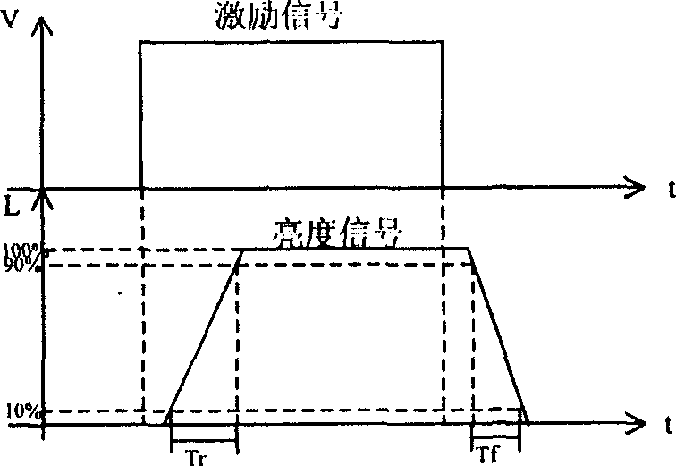
Liquid crystal display response time electrooptical automatic measuring instrument
A technology of liquid crystal display and response time, which is applied in the field of photoelectric measuring instruments, can solve problems such as complex actual conditions, and achieve the effects of simple test methods, accurate test results, and elimination of measurement errors
- Summary
- Abstract
- Description
- Claims
- Application Information
AI Technical Summary
Problems solved by technology
Method used
Image

Examples
Embodiment Construction
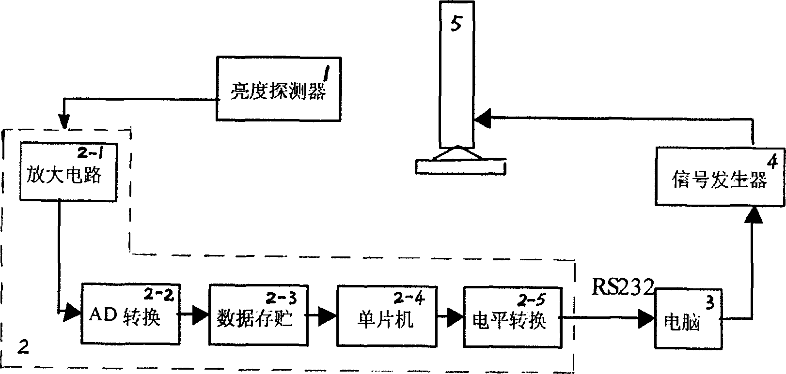
[0025] Such as figure 2 As shown, this embodiment is composed of a brightness detector 1, a data acquisition board 2, a computer 3, a signal generator 4 and a liquid crystal display 5.
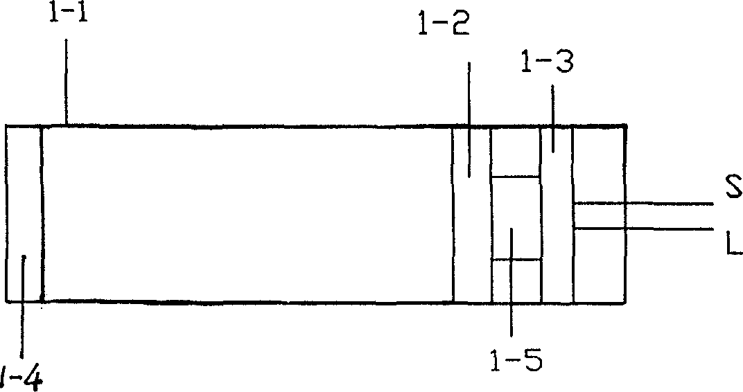
[0026] Such as image 3 As shown, the brightness detector 1 is used to convert the brightness signal into an electrical signal, and it includes a light cylinder 1-1, a color filter 1-2, a preamplifier circuit 1-3, a light bar 1-4 and a silicon photocell 1- 5. The light bar 1-4 is set at the input end of the light tube 1-1, the color filter 1-2 is set at the output end of the light tube 1-1, and the photoelectric signal is converted by the silicon photocell 1-5, and the converted The electrical signal enters the preamplifier circuit 1-3 to be amplified (see Figure 4 shown), the preamplifier circuit adopts the amplifier OP07, and its output signal is output to the amplifier circuit 2-1 in the data acquisition board 2 through the signal line S (see Figure 5 shown), from IC U 5 (Model OP07)...
PUM
 Abstract
Description
Claims
Application Information